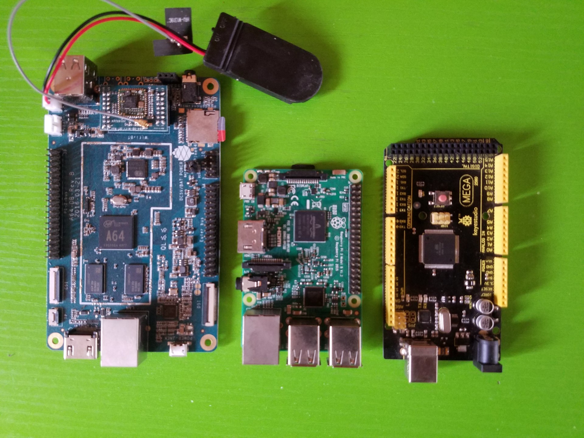
Although the PINE64 provides quite a decent number of GPIO pins, there are several reasons that you may want to have access to more pins. For example, the Arduino can provide an extra number of native PWM pins, or you may want to implement low-level control of a robot using the Arduino, with high-level operations being handled by the PINE. This post will cover how this can be achieved with the PINE64 and an Arduino Mega. We’ll also create a sketch for the Mega which for handling I2C communication. In the next post, we will write some C and C# code which will show how to send and receive data between the PINE and the Mega. Note that this can be done with any single board computer that supports I2C including any of the Raspberry Pis, the Beagleboard and others.
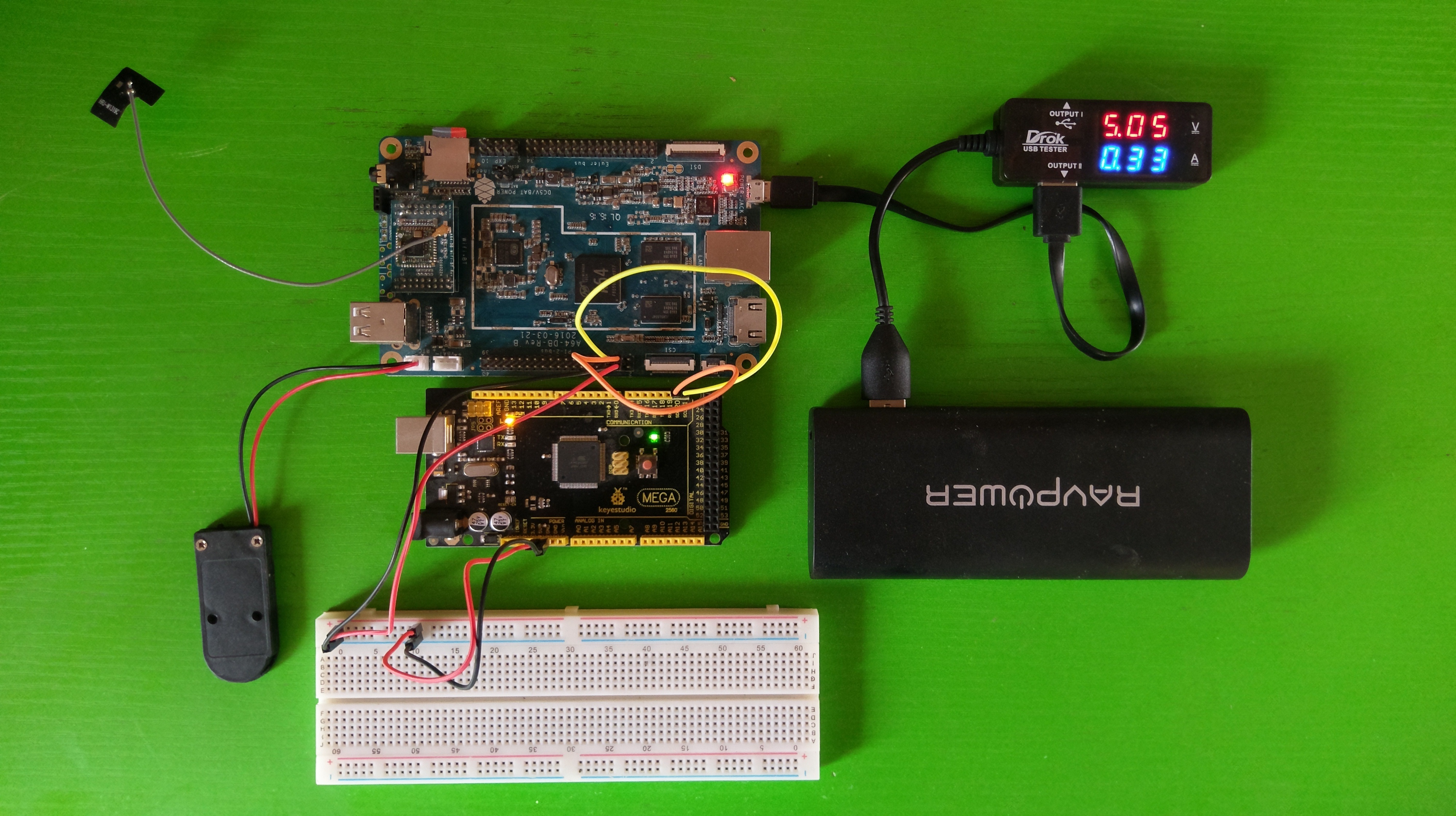
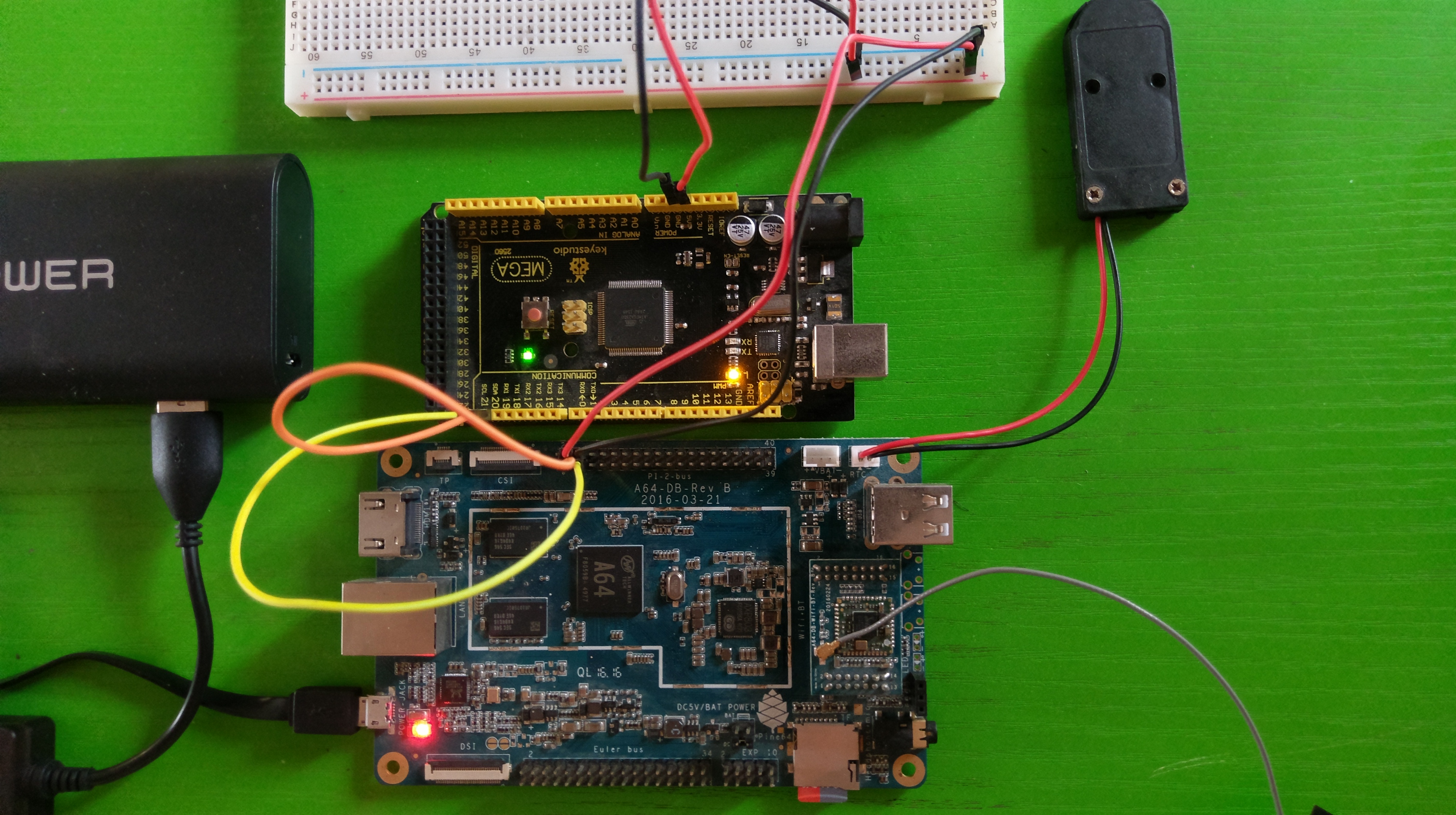
PINE64 connected to Arduino Mega over I2C
I2C stands for Inter-Integrated Circuit and it is a serial computer bus that enables communication between multiple devices that support the protocol. Every board that supports I2C will have 2 pins called SDA (serial data line) and SCL (serial clock line).
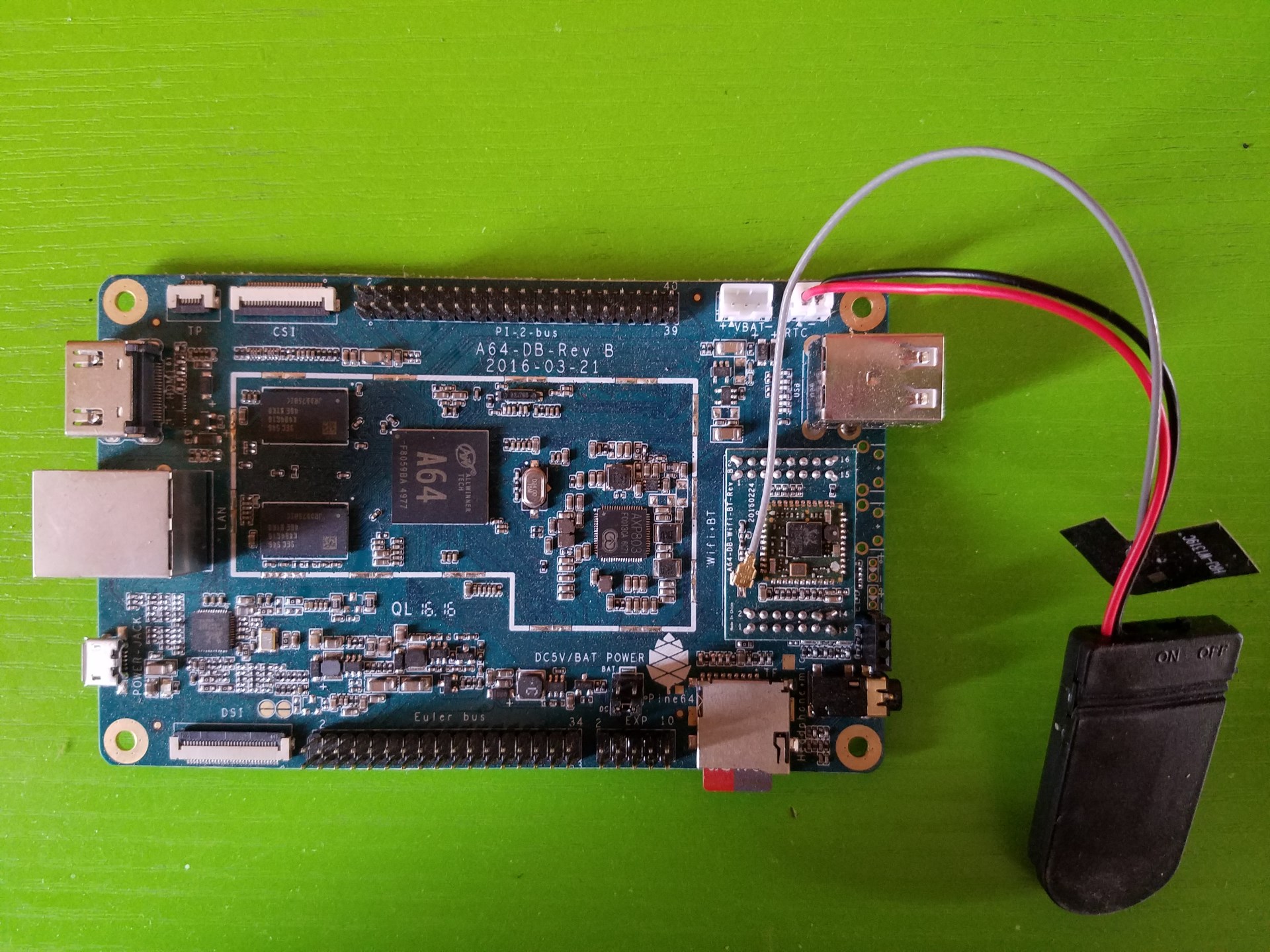
Pins 3 and 5 of the Pi 2 pinout on the PINE64 are the SDA and SCL pins respectively. On the Mega, they are pins 20 and 21. Connect the SDA and SCL pins from the PINE64 to the SDA and SCL pins respectively on the Arduino. I have also connected the 5V from the PINE to the Mega in order for the Mega to be powered by the PINE. If you decide to take this approach, one of the ground pins also has to be connected between both boards.
A closer look at the I2C connection between the PINE64 and the Arduino Mega
Before connecting the Mega, we’ll need to create and upload a sketch that will assign an I2C address which will be used to access the device. The sketch will make use of the Wire library which will be used for I2C communication. We will be making use of byte arrays to send and receive data over the I2C bus. You can come up with a fancy protocol for this, but I came up with the following simple rules.
- Maximum length of 16 bytes.
- First byte will always be the length (inclusive of the first byte) of the data sent or received.
- Second byte is the command. We’ll support 3 simple commands, digital write (0x01 or 1), digital read (0x02 or 2) and analog write (0x03 or 3).
- Third byte is the pin number.
- For digital write only, fourth byte be a value of either 1 (for high) or 0 (for low).
- For analog write only, the next four bytes after the third byte will store an integer value between 0 and 255 inclusive.
With that out of the way, let’s take a look at the sketch. First things first, define our constants and variables.
1 2 3 4 5 6 7 8 9 10 11 12 13 14 15 16 17 18 19 20 21 22 23 24 25 26 27 28 | #include <Wire.h> // I2C slave address #define I2C_ADDRESS 0x08 // Custom I2C data commands #define CMD_DIGITAL_WRITE 0x01 #define CMD_DIGITAL_READ 0x02 #define CMD_ANALOG_WRITE 0x03 // Pin states #define IO_PIN_STATE_INPUT 0x01 #define IO_PIN_STATE_OUTPUT 0x02 // Buffer for reading and writing data from/to I2C unsigned char bytes[16]; unsigned char sendBytes[5]; int analogValue = 0; int lastReadCommand = 0; int lastReadPin = 0; int thisPin = 0; int ioPinStates[53]; // pseudo hashmap const int ioPinCount = 40; const int ioPins[] = { 2, 3, 4, 5, 6, 7, 8, 9, 10, 11, 12, 13, 23, 24, 25, 26, 27, 28, 29, 30, 31, 32, 33, 34, 35, 36, 37, 38, 39, 40, 41, 42, 43, 44, 45, 46, 47, 48, 49, 50, 51, 52 }; |
The code is straightforward. We define 0x08 as the I2C address that we want the Mega to use. We also define our commands, pin states (for digital read / write), buffers for storing data to be sent and received and other variables that will be used. The ioPins array is a list of all the pins available on the Mega. This will need to be changed to match the board that the sketch will be uploaded to. The ioPinStates is a pseudo hashmap which will map the pin number (used as the array index) to one of the defined pin states (IO_PIN_STATE_INPUT or IO_PIN_STATE_OUTPUT). We’re keeping track of the pin states so that we can activate the pins on demand, instead of activating them all at once in the setup() function.
1 2 3 4 5 6 7 8 9 10 11 12 13 14 15 16 17 18 19 20 21 22 | void setup() { // put your setup code here, to run once: Wire.begin(I2C_ADDRESS); Serial.begin(9600); Wire.onReceive(onDataReceived); Wire.onRequest(onDataRequested); } void loop() { } bool isPinValid(int pin) { for (int i = 0; i < ioPinCount; i++) { if (ioPins[i] == pin) { return true; } } return false; } |
The setup function simply initialises the Wire library using the specified I2C address, and enables Serial output which will be used to output debug messages. Wire.onReceive registers the onDataReceived function which will be called when data is sent from the PINE64, while Wire.onRequest registers the onDataRequested function which will be called when the PINE64 requests data from the Mega. The isPinValid function is a helper method which checks if the pin specified as the parameter is valid for the board. It checks the pin against the ioPins array that we defined earlier.
Next is the onDataReceived function which handles most of the work. It accepts an argument which represents the number of bytes that were received.
1 2 3 4 5 6 7 8 9 10 11 12 13 | void onDataReceived(int byteCount) { int i = 0; int idx = 0; while (Wire.available()) { bytes[idx] = Wire.read(); if ((idx + 1) == bytes[0]) { // Length received int len = (int) bytes[0]; if (len < 3) { Serial.print("Invalid data received."); return; } |
The while loop checks if there is data available from the Wire library. If there is, the absolute minimum number of bytes received that can be considered valid based on the rules we defined earlier is 3 (length, command, pin). If the number of bytes received is less than 3, then the function ends at that point and output is written to the Serial console. The next step is to use a switch statement to check and handle the command that was received. The second byte (index 1) contains this data.
1 2 3 4 5 6 7 8 9 10 11 12 13 14 15 16 17 18 19 20 21 22 | switch (bytes[1]) { case CMD_DIGITAL_WRITE: if (len < 4) { Serial.println("Incomplete digital write data."); return; } thisPin = (int) bytes[2]; if (!isPinValid(thisPin)) { Serial.println("Invalid pin specified for digital write."); return; } // do digital write if (ioPinStates[thisPin] != IO_PIN_STATE_OUTPUT) { pinMode(thisPin, OUTPUT); ioPinStates[thisPin] = IO_PIN_STATE_OUTPUT; } digitalWrite(thisPin, bytes[3]); break; |
For digital write, the minimum number of bytes to be considered valid is 4 (length, command, pin, value). The function is terminated if we received less than 4 bytes for the command. The isPinValid is called to check if the pin received is valid, and if it isn’t, the function ends at that point. Next thing to be done is to check if the pin has been activated. We make use of the ioPinStates array to do this making use of the pin number as the index. If the pin has not yet been activated (IO_PIN_STATE_OUTPUT), then we activate the pin using pinMode. Once this check is complete, we can call digitalWrite using the pin and the value specified.
1 2 3 4 5 6 7 8 9 10 11 12 13 14 15 16 17 18 19 20 21 | case CMD_DIGITAL_READ: if (len < 3) { Serial.println("Incomplete digital read data."); return; } thisPin = (int) bytes[2]; if (!isPinValid(thisPin)) { Serial.println("Invalid pin specified for digital read."); return; } if (ioPinStates[thisPin] != IO_PIN_STATE_OUTPUT) { pinMode(thisPin, OUTPUT); ioPinStates[thisPin] = IO_PIN_STATE_OUTPUT; } lastReadCommand = CMD_DIGITAL_READ; lastReadPin = thisPin; break; |
Digital read also follows the same set of steps as digital write (validate date length, validate pin, check pin state) but we will call the actual digitalRead function in onDataRequested. What we do here is store the command and the pin in variables (lastReadCommand and lastReadPin respectively) which we can then make use of in onDataRequested.
1 2 3 4 5 6 7 8 9 10 11 12 13 14 15 16 17 18 19 20 21 22 23 24 25 26 27 | case CMD_ANALOG_WRITE: if (len < 7) { Serial.println("Incomplete analog write data."); return; } thisPin = (int) bytes[2]; if (!isPinValid(thisPin)) { Serial.println("Invalid pin specified for analog write."); return; } analogValue = 0; analogValue = (uint32_t) bytes[3] << 24; analogValue |= (uint32_t) bytes[4] << 16; analogValue |= (uint32_t) bytes[5] << 8; analogValue |= (uint32_t) bytes[6]; if (analogValue < 0 || analogValue > 255) { Serial.println("Invalid value specified for analog write."); return; } analogWrite(thisPin, analogValue); break; |
Similar to digital write, analog write follows a couple of steps (validate data length and validate pin). We don’t need to check or set the pin state before calling the analogWrite function. We check that the value is between 0 and 255 inclusive before calling analogWrite with the pin and the value as the arguments.
1 2 3 4 5 6 7 8 9 10 11 | default: Serial.println("Unrecognised command."); break; } idx = 0; } idx++; } } |
If the data sent did not match any of the defined commands, the code falls back to the default statement which outputs Unrecognised command. to the serial command, and then the onDataReceived function will be called again when new data is received.
Finally, we have the onDataRequested function which makes use of lastReadCommand and lastReadPin. The function is straightforward, as it uses the Wire library to send data back to the PINE following our simple rules.
1 2 3 4 5 6 7 8 9 10 11 12 | void onDataRequested() { switch (lastReadCommand) { case CMD_DIGITAL_READ: // Send the value over I2C sendBytes[0] = 3; // length sendBytes[1] = lastReadPin; // the pin that was read sendBytes[2] = digitalRead(lastReadPin); // the pin value (0/1) Wire.write(sendBytes, sendBytes[0]); break; } } |
And that’s it! Compile the sketch using the Arduino IDE and then upload it to your board. Connect your Arduino to the PINE after the sketch is successfully uploaded, and boot up the PINE. You can obtain the full code listing for the sketch at https://gitlab.com/akinwale/nanitei2c/blob/master/nanitei2c_mega.ino.
Install i2c-tools using sudo apt-get install i2c-tools. By default, only root can use the I2C commands, but you can add the user account with useradd -G i2c ubuntu (replace ubuntu with the username that you want to use to access I2C). Reboot the PINE and then scan the I2C bus with the command, i2cdetect -y 1. You should get output should be similar to the following:
1 2 3 4 5 6 7 8 9 | 0 1 2 3 4 5 6 7 8 9 a b c d e f 00: -- -- -- -- -- 08 -- -- -- -- -- -- -- 10: -- -- -- -- -- -- -- -- -- -- -- -- -- -- -- -- 20: -- -- -- -- -- -- -- -- -- -- -- -- -- -- -- -- 30: -- -- -- -- -- -- -- -- -- -- -- -- -- -- -- -- 40: -- -- -- -- -- -- -- -- -- -- -- -- -- -- -- -- 50: -- -- -- -- -- -- -- -- -- -- -- -- -- -- -- -- 60: -- -- -- -- -- -- -- -- -- -- -- -- -- -- -- -- 70: -- -- -- -- -- -- -- -- |
Based on this output, we can see that the Mega was recognised over the I2C bus with the configured address in our sketch (0x08 or 8). With this, we have access to the extra pins which we will be able to control directly from the PINE. That’s pretty neat. In the next post, we will write the C and C# code for the PINE for handling I2C communication.