I took the IELTS exam a couple of years ago as part of my plans to apply for the Canadian Express Entry programme, and the results are about to expire. It is a weird concept that I have to re-take an exam to demonstrate my competence with a language that I have been speaking since I was born. Of course, it’s the same fee for admission, which is also just as frustrating. Then again, it is something that I have to do.
I’ve also spent the past few weeks trying to decide if I should just build a new desktop computer altogether (since my AMD Ryzen 7 2700 build is over 6 years old now), or build a separate Hackintosh machine. I managed to create a cheap build that’s a spec-to-spec match for the M2 Pro Mac mini which comes in at just about $850. A fully decked out desktop replacement that I liked would’ve been about $1600 (just $400 over my initial theory-crafted Hackintosh build). I could’ve pulled the trigger on that, but Intel’s next gen processors (Meteor Lake and Arrow Lake) which are around the corner will be using a new socket platform: LGA1851, instead of LGA1700. It doesn’t seem like a great idea to splurge on a new machine when there is no viable future upgrade path. And I do need Intel, so that I can run the Android simulator on the Hackintosh build. Virtualisation software do not like AMD processors in this scenario, unfortunately.
With my desktop replacement plans pushed further into the future, here’s the final cheap Hackintosh build I’ve arrived at. I already own a 1000W PSU back from my short-lived crypto mining days, and I purchased a RX 6600 just recently for my AMD build, for full graphics acceleration support. It can be $120 – $150 cheaper if I opt to go with DDR4 memory, but I think I like it this way. Sidenote: Why are DDR5 motherboards so goddamn expensive?!
Oh look, Mr. Inconsistent Blog Poster is back. But let’s not have that conversation right now. I know I’ve promised several times to post more regularly, but I am clearly a disappointment to myself. Just to get a few life updates out of the way: I am currently unemployed, looking for work. I learned French, up to the B2 level and I’m planning to take either the TEF or TCF exam soon. And I completed a 3-year university program with BCS in 2 years. I also created a buymeacoffee profile, but for sandwiches, so if you’d like to support the content creation journey which I’m about to re-embark upon, it’ll be much appreciated. Cool? Cool.
Alright, I need to replace my late 2012 Mac mini. I’ve gone back to doing some React Native development recently (existing codebase, not by choice, but there’s money to be made), especially targeting iOS devices, and the mini just doesn’t cut it anymore. I had heard good things about the M2 Pro processor, and I was considering a replacement Mac mini, but the prices for the configuration are just too goddamn high! I initially thought that the 2012 mini was at the end of life due to the fact that I needed to run XCode 14.2, which only works on the official macOS releases that run on Apple Silicon. However, I was able to actually upgrade from Catalina to Big Sur (using Patched Sur), and then from Big Sur to Monterey (using OpenCore). The bad news is everything runs quite slowly, but I had a lightbulb moment!
The late 2012 Mac mini is a machine with an Intel CPU, which means if I could get the latest release of Apple running on that, then I should be able to get it working on other Intel machines as well. The bigger surprise? I was actually able to get Monterey 12.6.4 running on my AMD build (considering I haven’t purchased Intel for over 6 years now). The spec sheet: Ryzen 2700 with 32GB of DDR4 RAM, ASRock B450M Pro4 motherboard, NVIDIA Geforce RTX 2060 graphics and a spare 500GB Crucial MX500 SSD I had lying around. It actually worked (EFI here if you’re interested), but there’s no hardware acceleration due to the fact that NVIDIA GPU support has been dropped from macOS, so I have to manage until I can afford to purchase an AMD graphics card, which isn’t available locally. The plan is to get a cheap 5500XT which allegedly works great. Thing were looking good, then I decided to try out running an Android emulator, only to be greeted with a nasty error that virtualisation isn’t working, although I have SVM enabled in the BIOS. Turns out I need an Intel CPU to be able to get this to work.
The ideal Mac mini M2 Pro configuration that I was aiming for cost $2,199.
M2 Pro 12-Core CPU | 19-Core GPU
32GB Unified RAM
1TB SSD
Wi-Fi 6E (802.11ax) | Bluetooth 5.3
I/O: 4 x Thunderbolt 4 / USB4 ports, 1x USB-A 3.1 Gen 1, 1x HDMI, 3.5mm headphone jack, 1 x Gigabit Ethernet Port
I put together an Intel build on pcpartpicker matching spec for spec, including discrete graphics which practically costs half, and performs way better with the benchmark scores available online. Look, I get that inflation is crazy all over the world right now, but this Apple tax is just something else! And there’s no way I’m willing to pay anything close to that.
I’ve been growing wary of tinkering (looking at you, Linux) and building software from source as I have become older because things that just work make life easier, but I’m excited to get back into this once again considering what can be achieved. Thanks Apple!
I stumbled across a very interesting project called LBRY a while back, which I can describe as bitcoin meets bittorrent, Youtube and Soundcloud and and they all have a baby. The app includes a daemon developed in Python which is used to communicate with the LBRY network, and the goal was to get this running on Android one way or another. Prior to this, I had absolutely no idea there was a way to actually get Python on Android. I mean, it was theoretically possible since Android is based on Linux, but I had just never come across anything related to that.
Then I found out about Kivy, and the python for android (p4a) project. P4A makes use of a mechanism called recipes which define how certain Python modules or components should be built for a platform. There was a joint effort to get the daemon to compile and actually run on Android, which was eventually successful, but the Python version for the current p4a master branch is 2.7.2. I wasn’t exactly satisfied with this, so I went down the rabbit hole of getting Python 2.7.13 up and running. This took quite some time and effort, but I managed to get it to work. I found it to be quite frustrating at times, but it was also very exciting and I had a feeling of satisfaction after I had finished.
Funny story, after figuring it all out, I discovered there were pull requests created in Github for the p4a project related to building with Python version 2.7.11. If I had found them earlier, my life would have been a whole lot easier! Either way, it was a good learning experience and I’m glad to say it works pretty well.
You can find the LBRY Android project on Github if you’re interested in the recipes for building and running Python 2.7.13.
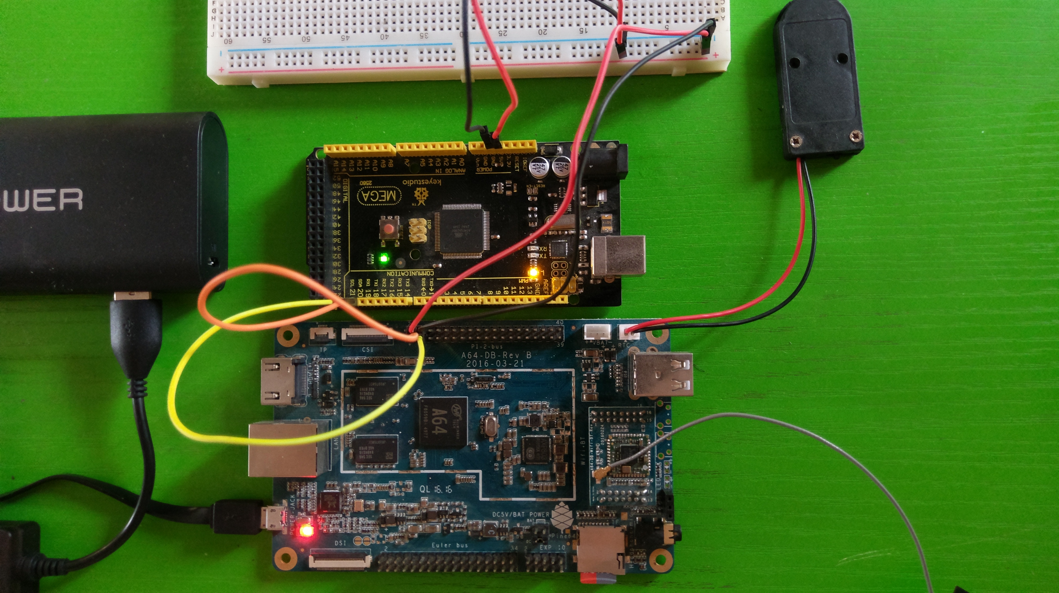
Although the PINE64 provides quite a decent number of GPIO pins, there are several reasons that you may want to have access to more pins. For example, the Arduino can provide an extra number of native PWM pins, or you may want to implement low-level control of a robot using the Arduino, with high-level operations being handled by the PINE. This post will cover how this can be achieved with the PINE64 and an Arduino Mega. We’ll also create a sketch for the Mega which for handling I2C communication. In the next post, we will write some C and C# code which will show how to send and receive data between the PINE and the Mega. Note that this can be done with any single board computer that supports I2C including any of the Raspberry Pis, the Beagleboard and others.
PINE64 connected to Arduino Mega over I2C
I2C stands for Inter-Integrated Circuit and it is a serial computer bus that enables communication between multiple devices that support the protocol. Every board that supports I2C will have 2 pins called SDA (serial data line) and SCL (serial clock line).
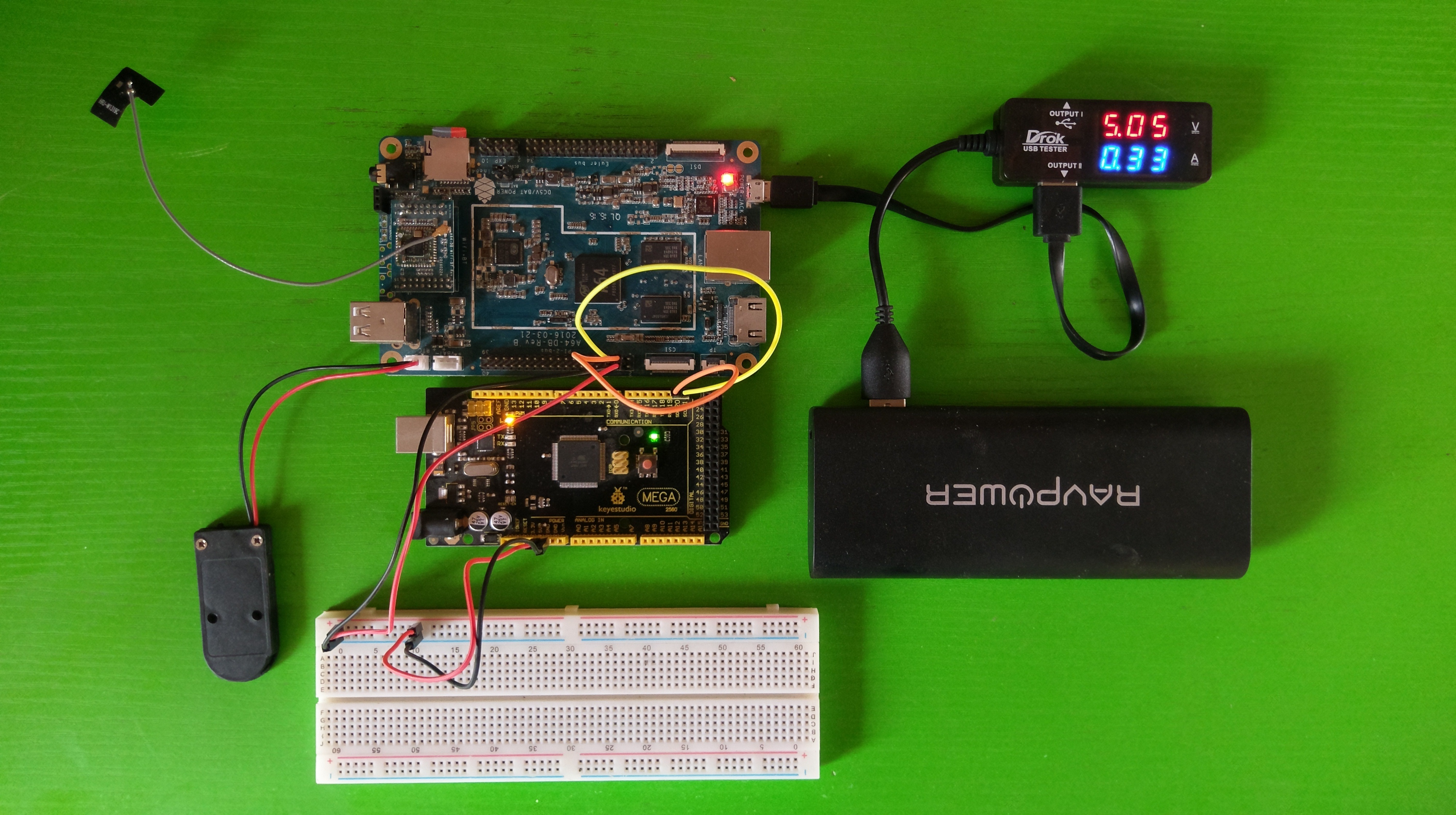
Pins 3 and 5 of the Pi 2 pinout on the PINE64 are the SDA and SCL pins respectively. On the Mega, they are pins 20 and 21. Connect the SDA and SCL pins from the PINE64 to the SDA and SCL pins respectively on the Arduino. I have also connected the 5V from the PINE to the Mega in order for the Mega to be powered by the PINE. If you decide to take this approach, one of the ground pins also has to be connected between both boards.
A closer look at the I2C connection between the PINE64 and the Arduino Mega
Before connecting the Mega, we’ll need to create and upload a sketch that will assign an I2C address which will be used to access the device. The sketch will make use of the Wire library which will be used for I2C communication. We will be making use of byte arrays to send and receive data over the I2C bus. You can come up with a fancy protocol for this, but I came up with the following simple rules.
Maximum length of 16 bytes.
First byte will always be the length (inclusive of the first byte) of the data sent or received.
Second byte is the command. We’ll support 3 simple commands, digital write (0x01 or 1), digital read (0x02 or 2) and analog write (0x03 or 3).
Third byte is the pin number.
For digital write only, fourth byte be a value of either 1 (for high) or 0 (for low).
For analog write only, the next four bytes after the third byte will store an integer value between 0 and 255 inclusive.
With that out of the way, let’s take a look at the sketch. First things first, define our constants and variables.
1
2
3
4
5
6
7
8
9
10
11
12
13
14
15
16
17
18
19
20
21
22
23
24
25
26
27
28
#include <Wire.h>
// I2C slave address
#define I2C_ADDRESS 0x08
// Custom I2C data commands
#define CMD_DIGITAL_WRITE 0x01
#define CMD_DIGITAL_READ 0x02
#define CMD_ANALOG_WRITE 0x03
// Pin states
#define IO_PIN_STATE_INPUT 0x01
#define IO_PIN_STATE_OUTPUT 0x02
// Buffer for reading and writing data from/to I2C
The code is straightforward. We define 0x08 as the I2C address that we want the Mega to use. We also define our commands, pin states (for digital read / write), buffers for storing data to be sent and received and other variables that will be used. The ioPins array is a list of all the pins available on the Mega. This will need to be changed to match the board that the sketch will be uploaded to. The ioPinStates is a pseudo hashmap which will map the pin number (used as the array index) to one of the defined pin states (IO_PIN_STATE_INPUT or IO_PIN_STATE_OUTPUT). We’re keeping track of the pin states so that we can activate the pins on demand, instead of activating them all at once in the setup() function.
1
2
3
4
5
6
7
8
9
10
11
12
13
14
15
16
17
18
19
20
21
22
voidsetup(){
// put your setup code here, to run once:
Wire.begin(I2C_ADDRESS);
Serial.begin(9600);
Wire.onReceive(onDataReceived);
Wire.onRequest(onDataRequested);
}
voidloop(){
}
boolisPinValid(intpin){
for(inti=0;i<ioPinCount;i++){
if(ioPins[i]==pin){
returntrue;
}
}
returnfalse;
}
The setup function simply initialises the Wire library using the specified I2C address, and enables Serial output which will be used to output debug messages. Wire.onReceive registers the onDataReceived function which will be called when data is sent from the PINE64, while Wire.onRequest registers the onDataRequested function which will be called when the PINE64 requests data from the Mega. The isPinValid function is a helper method which checks if the pin specified as the parameter is valid for the board. It checks the pin against the ioPins array that we defined earlier.
Next is the onDataReceived function which handles most of the work. It accepts an argument which represents the number of bytes that were received.
1
2
3
4
5
6
7
8
9
10
11
12
13
voidonDataReceived(intbyteCount){
inti=0;
intidx=0;
while(Wire.available()){
bytes[idx]=Wire.read();
if((idx+1)==bytes[0]){// Length received
intlen=(int)bytes[0];
if(len<3){
Serial.print("Invalid data received.");
return;
}
The while loop checks if there is data available from the Wire library. If there is, the absolute minimum number of bytes received that can be considered valid based on the rules we defined earlier is 3 (length, command, pin). If the number of bytes received is less than 3, then the function ends at that point and output is written to the Serial console. The next step is to use a switch statement to check and handle the command that was received. The second byte (index 1) contains this data.
1
2
3
4
5
6
7
8
9
10
11
12
13
14
15
16
17
18
19
20
21
22
switch(bytes[1]){
caseCMD_DIGITAL_WRITE:
if(len<4){
Serial.println("Incomplete digital write data.");
return;
}
thisPin=(int)bytes[2];
if(!isPinValid(thisPin)){
Serial.println("Invalid pin specified for digital write.");
return;
}
// do digital write
if(ioPinStates[thisPin]!=IO_PIN_STATE_OUTPUT){
pinMode(thisPin,OUTPUT);
ioPinStates[thisPin]=IO_PIN_STATE_OUTPUT;
}
digitalWrite(thisPin,bytes[3]);
break;
For digital write, the minimum number of bytes to be considered valid is 4 (length, command, pin, value). The function is terminated if we received less than 4 bytes for the command. The isPinValid is called to check if the pin received is valid, and if it isn’t, the function ends at that point. Next thing to be done is to check if the pin has been activated. We make use of the ioPinStates array to do this making use of the pin number as the index. If the pin has not yet been activated (IO_PIN_STATE_OUTPUT), then we activate the pin using pinMode. Once this check is complete, we can call digitalWrite using the pin and the value specified.
1
2
3
4
5
6
7
8
9
10
11
12
13
14
15
16
17
18
19
20
21
caseCMD_DIGITAL_READ:
if(len<3){
Serial.println("Incomplete digital read data.");
return;
}
thisPin=(int)bytes[2];
if(!isPinValid(thisPin)){
Serial.println("Invalid pin specified for digital read.");
return;
}
if(ioPinStates[thisPin]!=IO_PIN_STATE_OUTPUT){
pinMode(thisPin,OUTPUT);
ioPinStates[thisPin]=IO_PIN_STATE_OUTPUT;
}
lastReadCommand=CMD_DIGITAL_READ;
lastReadPin=thisPin;
break;
Digital read also follows the same set of steps as digital write (validate date length, validate pin, check pin state) but we will call the actual digitalRead function in onDataRequested. What we do here is store the command and the pin in variables (lastReadCommand and lastReadPin respectively) which we can then make use of in onDataRequested.
1
2
3
4
5
6
7
8
9
10
11
12
13
14
15
16
17
18
19
20
21
22
23
24
25
26
27
caseCMD_ANALOG_WRITE:
if(len<7){
Serial.println("Incomplete analog write data.");
return;
}
thisPin=(int)bytes[2];
if(!isPinValid(thisPin)){
Serial.println("Invalid pin specified for analog write.");
return;
}
analogValue=0;
analogValue=(uint32_t)bytes[3]<<24;
analogValue|=(uint32_t)bytes[4]<<16;
analogValue|=(uint32_t)bytes[5]<<8;
analogValue|=(uint32_t)bytes[6];
if(analogValue<0||analogValue>255){
Serial.println("Invalid value specified for analog write.");
return;
}
analogWrite(thisPin,analogValue);
break;
Similar to digital write, analog write follows a couple of steps (validate data length and validate pin). We don’t need to check or set the pin state before calling the analogWrite function. We check that the value is between 0 and 255 inclusive before calling analogWrite with the pin and the value as the arguments.
1
2
3
4
5
6
7
8
9
10
11
default:
Serial.println("Unrecognised command.");
break;
}
idx=0;
}
idx++;
}
}
If the data sent did not match any of the defined commands, the code falls back to the default statement which outputs Unrecognised command. to the serial command, and then the onDataReceived function will be called again when new data is received.
Finally, we have the onDataRequested function which makes use of lastReadCommand and lastReadPin. The function is straightforward, as it uses the Wire library to send data back to the PINE following our simple rules.
1
2
3
4
5
6
7
8
9
10
11
12
voidonDataRequested(){
switch(lastReadCommand)
{
caseCMD_DIGITAL_READ:
// Send the value over I2C
sendBytes[0]=3;// length
sendBytes[1]=lastReadPin;// the pin that was read
sendBytes[2]=digitalRead(lastReadPin);// the pin value (0/1)
Wire.write(sendBytes,sendBytes[0]);
break;
}
}
And that’s it! Compile the sketch using the Arduino IDE and then upload it to your board. Connect your Arduino to the PINE after the sketch is successfully uploaded, and boot up the PINE. You can obtain the full code listing for the sketch at https://gitlab.com/akinwale/nanitei2c/blob/master/nanitei2c_mega.ino.
Install i2c-tools using sudo apt-get install i2c-tools. By default, only root can use the I2C commands, but you can add the user account with useradd -G i2c ubuntu (replace ubuntu with the username that you want to use to access I2C). Reboot the PINE and then scan the I2C bus with the command, i2cdetect -y 1. You should get output should be similar to the following:
1
2
3
4
5
6
7
8
9
0123456789abcdef
00:----------08--------------
10:--------------------------------
20:--------------------------------
30:--------------------------------
40:--------------------------------
50:--------------------------------
60:--------------------------------
70:----------------
Based on this output, we can see that the Mega was recognised over the I2C bus with the configured address in our sketch (0x08 or 8). With this, we have access to the extra pins which we will be able to control directly from the PINE. That’s pretty neat. In the next post, we will write the C and C# code for the PINE for handling I2C communication.