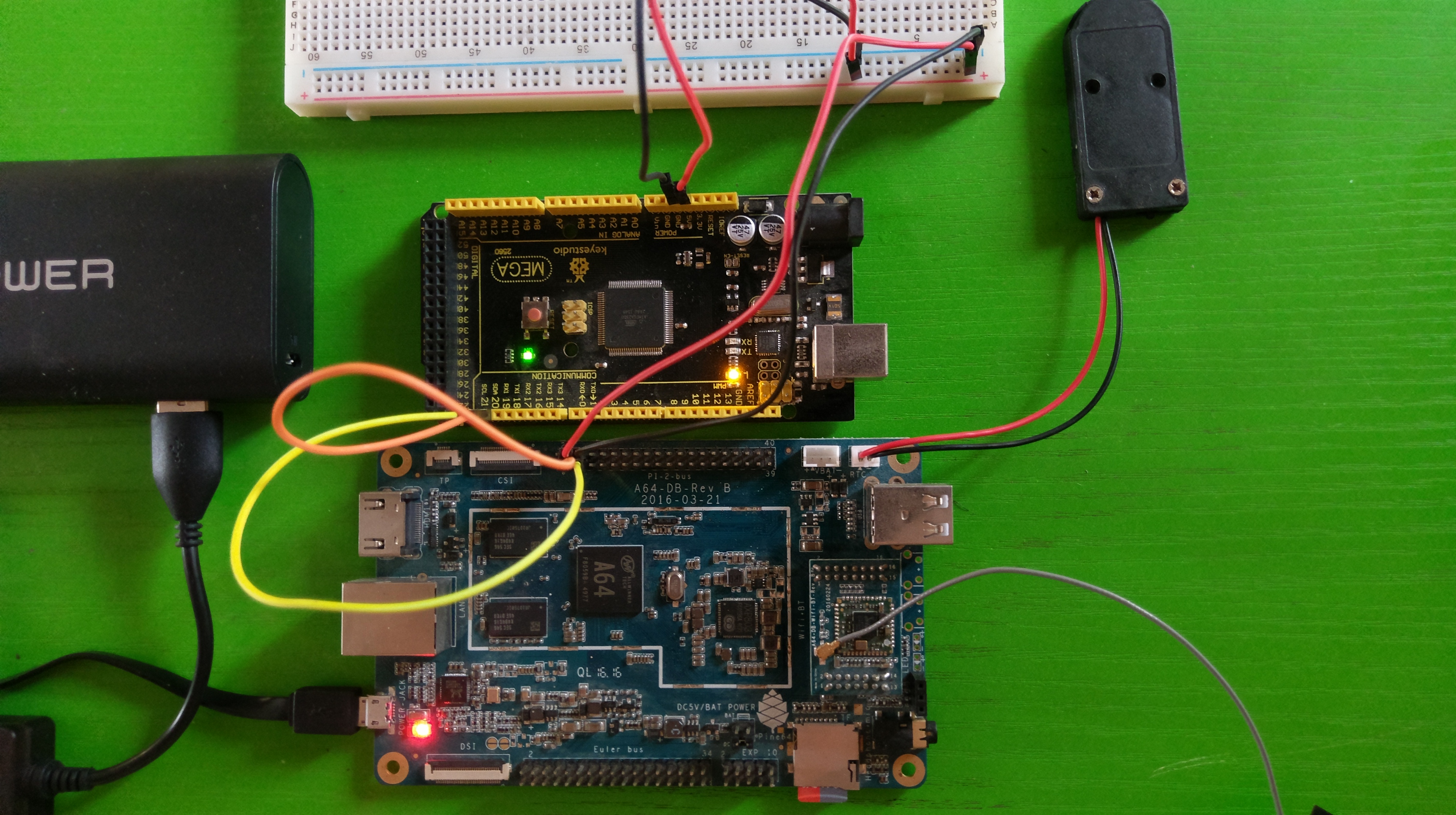
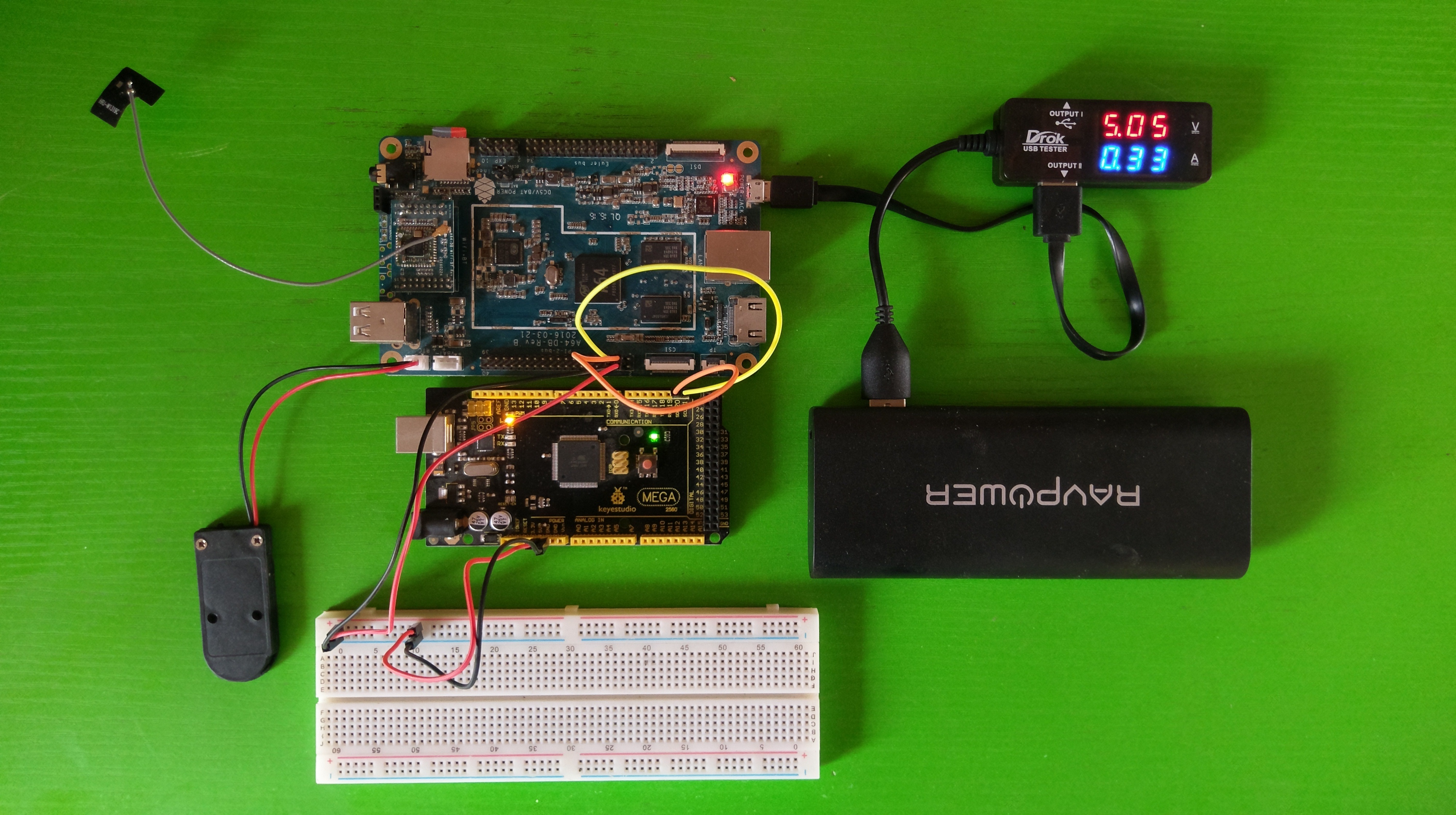
In a previous post, we connected an Arduino Mega to the PINE64 and wrote a sketch for the Mega for data communication. The data to be sent and received will follow the simple rules which were listed in the post. Next, we’re going to write a shared library with some C code to interface with I2C natively, and then a C# class which will call the shared library and bring everything together. Just a quick recap of the data rules:
- Maximum length: 16 bytes.
- First byte: Number of bytes sent/received.
- Second byte: Control command.
CMD_DIGITAL_WRITE(0x01 or 1),CMD_DIGITAL_READ(0x02 or 2) andCMD_ANALOG_WRITE(0x03 or 3). - Third byte: Pin number.
- Fourth byte: Value of either 1 (for high) or 0 (for low) for
CMD_DIGITAL_WRITE, or - Fourth to seventh bytes: Integer value for
CMD_ANALOG_WRITE.
Linux has native I2C support which lets us communicate directly with any device connected to the bus. Since native communication is possible, we create a shared library with methods which can be invoked from our C# code. Since we can open the connection to a device on the I2C bus as a file descriptor, we will be making use of fcntl.h for the descriptor. Let’s take a look at the C library.
1 2 3 4 5 6 7 8 9 10 11 12 13 14 15 16 17 18 19 20 21 22 23 24 25 | #include <fcntl.h> #include <unistd.h> #include <linux/i2c-dev.h> #define MAX_BYTES 16 /** * Open an I2C connection using the specified file descriptor. */ int nanite_i2c_open(const char *filename, int slave_address) { int fd; if ((fd = open(filename, O_RDWR)) < 0) { return -1; } if (ioctl(fd, I2C_SLAVE, slave_address) < 0) { return -1; } return fd; } |
The first thing we do is include required headers and define a constant specifying the maximum number of bytes, which is 16. Then we create the nanite_i2c_open function try to open the specified device file (usually /dev/i2c-1). Next we call ioctl so that we will be able to control the device using a reference to the file descriptor, and the specified slave address. The file descriptor is returned for reference in other function calls. If any of the steps in the function fails, -1 is returned to indicate an error condition. Other functions in the library will handle the failure the same way.
The nanite_i2c_close function is fairly simple. It takes the file descriptor as an argument and checks if it is open in order to close it.
1 2 3 4 5 6 7 8 9 10 11 12 | /** * Close the I2C connection using the specified file descriptor. */ int nanite_i2c_close(int fd) { if (fd > 0) { close(fd); } return 0; } |
Next is the nanite_i2c_send function which takes the file descriptor and the data to be sent as arguments. The bytes are written to the open file descriptor, and the number of bytes written is verified. If it does not match the length defined in the first byte, -1 is returned to indicate an error condition.
1 2 3 4 5 6 7 8 9 10 11 12 13 14 15 16 17 18 19 | /** * Send up to the maximum number of bytes over I2C using the specified file descriptor. */ int nanite_i2c_send(int fd, const char bytes[MAX_BYTES]) { if (fd <= 0 || !bytes) { return -1; } int num_bytes; num_bytes = write(fd, bytes, bytes[0]); if (num_bytes != bytes[0]) { return -1; } return num_bytes; } |
The nanite_i2c_read function will be used to read data over I2C. The first byte is retrieved in order to determine how many more bytes to read. Then we validate the number of bytes that were received with the expected length. 0 is returned if the operation was successful.
1 2 3 4 5 6 7 8 9 10 11 12 13 14 15 16 17 18 19 20 21 22 23 24 | /** * Read the byte data from I2C. */ int nanite_i2c_read(int fd, char bytes_read[MAX_BYTES]) { if (fd <= 0) { return -1; } char fbyte[1]; // Read the first byte to get the total number of bytes to read if (read(fd, fbyte, 1) != 1) { return -1; } if (read(fd, bytes_read, fbyte[0]) != fbyte[0]) { return -1; } return 0; } |
The final function in the library is nanite_i2c_max_bytes() which returns MAX_BYTES. This gives us a complete library that we can use for I2C data communication. You can create the shared library using gcc -shared -o libnanitei2c.so -fPIC main.c. The full code listing for the library is available at https://gitlab.com/akinwale/nanitei2c/blob/master/main.c.
Using DllImport, we can call functions from the shared library in the C# code which we’re going to look at next. We create our class, define the supported commands as an enumeration and specify the private members. We also define a couple of constructors with the default constructor using the default I2C device file which is /dev/i2c-1 on the PINE.
1 2 3 4 5 6 7 8 9 10 11 12 13 14 15 16 17 18 19 20 21 22 23 24 25 26 27 28 29 30 31 32 33 34 35 36 | using System; using System.Runtime.InteropServices; using Nanite.Exceptions; namespace Nanite.IO { /// <summary> /// /// </summary> public class I2CExtendedIO : IDisposable { public enum Commands { DigitalWrite = 1, DigitalRead = 2, AnalogWrite = 3 } private const string DefaultI2CFilename = "/dev/i2c-1"; private Object lockObject = new Object(); private int fileDescriptor; private string i2cFilename; public I2CExtendedIO(string i2cFilename) { this.i2cFilename = i2cFilename; } public I2CExtendedIO() : this(DefaultI2CFilename) { } |
The DllImport calls are defined within the class and are used to map the functions from the library to functions that we can call in the I2CExtendedIO class. For instance, to call the nanite_i2c_send in the class, we’ll make use of I2CSendBytes.
1 2 3 4 5 6 7 8 9 10 11 12 13 14 | [DllImport("libnanitei2c.so", EntryPoint="nanite_i2c_open")] internal static extern int OpenI2C(string filename, int slaveAddress); [DllImport("libnanitei2c.so", EntryPoint = "nanite_i2c_close")] internal static extern int CloseI2C(int fileDescriptor); [DllImport("libnanitei2c.so", EntryPoint = "nanite_i2c_send")] internal static extern int I2CSendBytes(int fileDescriptor, byte[] bytes); [DllImport("libnanitei2c.so", EntryPoint = "nanite_i2c_read")] internal static extern int I2CReadBytes(int fileDescriptor, byte[] bytesRead); [DllImport("libnanitei2c.so", EntryPoint = "nanite_i2c_max_bytes")] internal static extern int MaxByteCount(); |
Here, we’ve defined our class dispose function which closes the file descriptor if it is open. We also have a bunch of simple helper functions which will be called within the class.
1 2 3 4 5 6 7 8 9 10 11 12 13 14 15 16 17 18 19 20 21 22 23 24 25 26 27 28 29 30 31 32 33 34 35 36 37 38 39 40 41 42 43 44 45 46 47 48 49 50 51 52 53 | private void ValidateDigitalReadData(int pin, byte[] bytesReceived) { if (bytesReceived[0] < 3) { throw new ExtendedIOException("Invalid response data received over the I2C connection."); } if (bytesReceived[1] != pin) { throw new ExtendedIOException(string.Format("Pin mismatch for the DigitalRead command. Expected {0} but got {1}.", pin, bytesReceived[1])); } if (!IsGPIOValueValid(bytesReceived[2])) { throw new ExtendedIOException("The returned pin value is not valid."); } } private static bool IsGPIOValueValid(int value) { return ( (value == (int) GPIO.Value.Low) || (value == (int) GPIO.Value.High) ); } private void CheckFileDescriptor() { if (fileDescriptor <= 0) { throw new ExtendedIOException("I2C connection is not open."); } } public void Dispose() { Dispose(true); GC.SuppressFinalize(this); } ~I2CExtendedIO() { // Finalizer calls Dispose(false) Dispose(false); } protected virtual void Dispose(bool disposing) { // Close the file descriptor if it's open if (fileDescriptor > 0) { CloseI2C(fileDescriptor); fileDescriptor = -1; } } |
The Open function is simple as it delegates to the OpenI2C function with the specified device filename and the slave address, and assigns the returned file descriptor to a private member.
1 2 3 4 5 6 7 8 | public void Open(int slaveAddress) { fileDescriptor = OpenI2C(i2cFilename, slaveAddress); if (fileDescriptor <= 0) { throw new ExtendedIOException(string.Format("Unable to open the I2C connection to slave address: {0}", slaveAddress)); } } |
With DigitalWrite, we build the data to be sent based on the specified rules. Then we delegate to I2CSendBytes using the specified arguments, which calls the corresponding library function.
1 2 3 4 5 6 7 8 9 10 11 12 13 14 15 16 17 | public void DigitalWrite(int pin, GPIO.Value value) { CheckFileDescriptor(); // Build the command to send byte[] bytes = new byte[4]; bytes[0] = (byte) bytes.Length; bytes[1] = (byte) Commands.DigitalWrite; bytes[2] = (byte) pin; bytes[3] = (byte) value; int numBytes = I2CSendBytes(fileDescriptor, bytes); if (numBytes != bytes.Length) { throw new ExtendedIOException(string.Format("Could not send {0} bytes over the I2C connection.", bytes.Length)); } } |
AnalogWrite is similar to DigitalWrite, except that we convert the integer value to 4 bytes instead of the single byte for low (0) or high (1). Valid values are between 0 and 255 inclusive.
1 2 3 4 5 6 7 8 9 10 11 12 13 14 15 16 17 18 19 20 | public void AnalogWrite(int pin, int value) { CheckFileDescriptor(); // Build the command to send byte[] bytes = new byte[7]; bytes[0] = (byte) bytes.Length; bytes[1] = (byte) Commands.AnalogWrite; bytes[2] = (byte) pin; bytes[3] = (byte) (value >> 24); bytes[4] = (byte) (value >> 16); bytes[5] = (byte) (value >> 8); bytes[6] = (byte) value; int numBytes = I2CSendBytes(fileDescriptor, bytes); if (numBytes != bytes.Length) { throw new ExtendedIOException(string.Format("Could not send {0} bytes over the I2C connection.", bytes.Length)); } } |
To wrap it all up, we have the DigitalRead function which is a little different because we have to send data and then immediately receive a response. We obtain a mutual-exclusion lock so that the send and receive process completes before any subsequent operations are run. Then we validate the received data and return the value for the pin that was read.
1 2 3 4 5 6 7 8 9 10 11 12 13 14 15 16 17 18 19 20 21 22 23 24 25 26 27 28 29 30 31 32 33 34 35 36 37 38 39 40 41 | /// <summary> /// Reads the pin value /// /// Expected byte data always has a length of 3 /// bytesReceived[0] - the number of bytes /// bytesReceived[1] - the pin number /// bytesReceived[2] - the pin value /// </summary> /// <returns>GPIO.Value.High if the specified pin is HIGH, or GPIO.Value.Low if the specified pin is LOW.</returns> /// <param name="pin">Pin.</param> public GPIO.Value DigitalRead(int pin) { CheckFileDescriptor(); // Build the command to send byte[] bytes = new byte[3]; bytes[0] = (byte) bytes.Length; bytes[1] = (byte) Commands.DigitalRead; bytes[2] = (byte) pin; // The array to store received byte data byte[] bytesRecvd = new byte[MaxByteCount()]; // Obtain lock for send/receive lock (lockObject) { // Send the DigitalRead command int numBytes = I2CSendBytes(fileDescriptor, bytes); if (numBytes != bytes.Length) { throw new ExtendedIOException(string.Format("Could not send {0} bytes over the I2C connection.", bytes.Length)); } // Read the response immediately after the command I2CReadBytes(fileDescriptor, bytesRecvd); } ValidateDigitalReadData(pin, bytesRecvd); return (GPIO.Value) bytesRecvd[2]; } |
You can obtain the full code listing for the C# class at https://gitlab.com/akinwale/NaniteIo/blob/master/Nanite/IO/I2CExtendedIO.cs.
We can put this all together and test with a simple interactive console application.
1 2 3 4 5 6 7 8 9 10 11 12 13 14 15 16 17 18 19 20 21 22 23 24 25 26 27 28 29 30 31 32 33 34 35 36 37 38 39 40 41 42 43 44 45 46 47 48 49 50 51 52 53 54 55 56 57 58 59 60 61 62 63 64 65 66 | public static void Main (string[] args) { // Extended IO via I2C using (I2CExtendedIO eio = new I2CExtendedIO()) { try { eio.Open(0x08); string input; do { Console.Write("Enter PIN and value: "); input = Console.ReadLine(); if (input == "-1") { break; } string[] inputParts = input.Split(new char[] { ' ' }); if (inputParts.Length != 2 && inputParts.Length != 3) { Console.WriteLine("Invalid PIN and value. Try again."); continue; } try { int pin = int.Parse(inputParts[0].Trim()); string value = inputParts[1]; if (value != "off" && value != "on" && inputParts.Length == 2) { Console.WriteLine("Invalid PIN and value. Try again."); continue; } if (inputParts.Length == 3) { int analogValue = int.Parse(inputParts[2].Trim()); if (value != "analog") { Console.WriteLine("Invalid PIN and value. Try again."); continue; } eio.AnalogWrite(pin, analogValue); } else { eio.DigitalWrite(pin, "on" == value ? GPIO.Value.High : GPIO.Value.Low); } } catch (FormatException) { Console.WriteLine("Invalid PIN and value. Try again."); continue; } } while (input != "-1"); } catch (ExtendedIOException ex) { Console.WriteLine(ex.ToString()); } } } |
The console application accepts inputs like 13 on, 18 off or 9 analog 172 which makes it easy to test the Arduino pins. Although this is practically a complete solution for most requirements with respect to controlling an Arduino connected to the PINE (or Pi or any other SBC) over I2C using C#, you could choose to implement an additional command for analogRead. All you would have to do is follow the logic for digitalRead and add the necessary code to the sketch and the C# class.