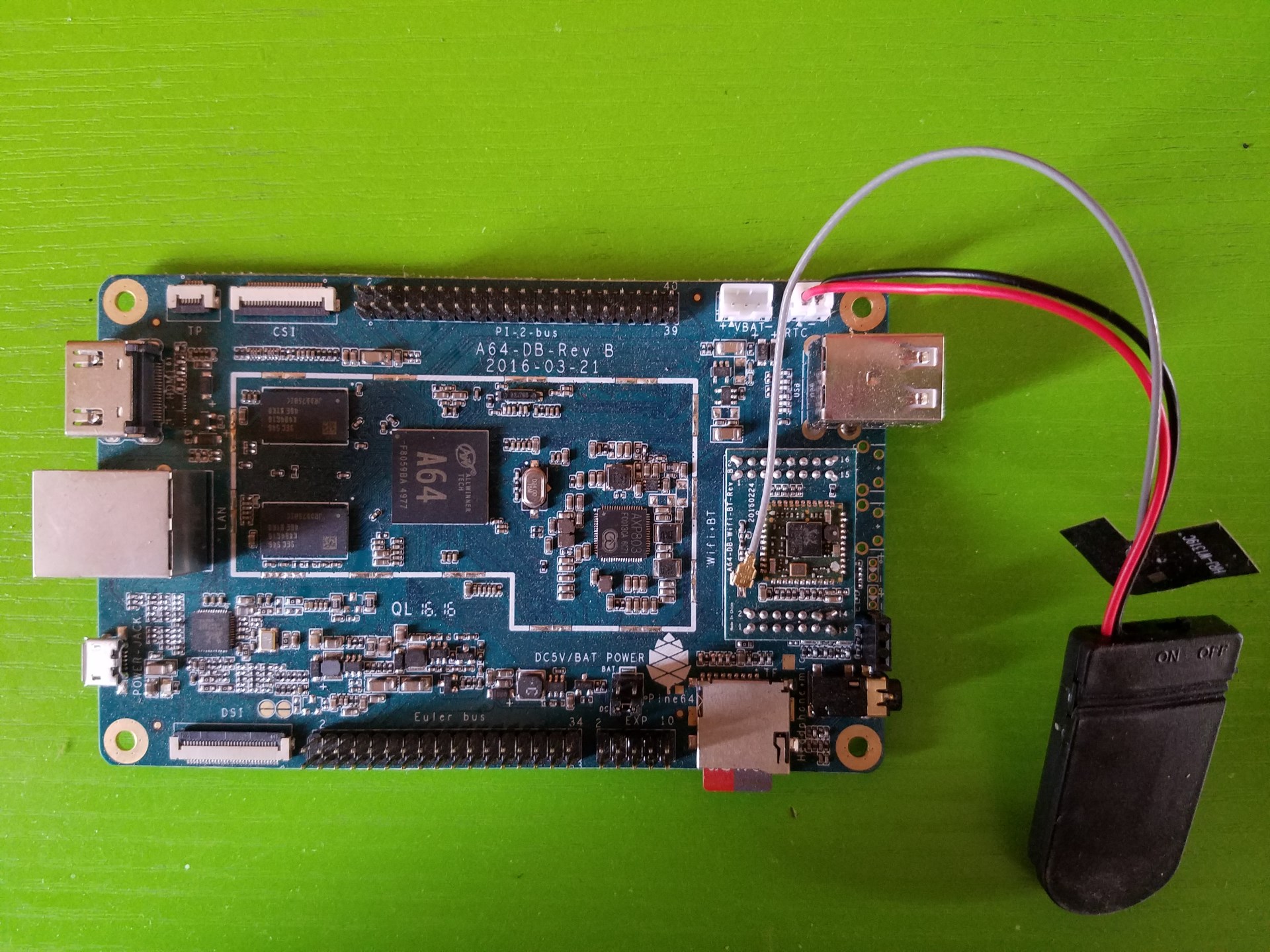
Although the goal of the autonomous robot project is to have a robot that can navigate without human input, it’s not a bad idea to be able to manually override and control the robot one way or another which could come in useful in cases where it gets stuck due to being trapped in between large physical obstacles, or perhaps a bug in the code. My PINE64 order came with the stock WiFi / Bluetooth 4.0 module which is still available from the PINE store, and I also got the Xbox Wireless Controller with bluetooth support![]() ($39.99). Any bluetooth controller
($39.99). Any bluetooth controller![]() should be able to get the job done, but I particularly like the look of the Xbox Wireless controller. However, it was a little difficult getting the controller to actually pair due to certain quirks with the controller implementation. I finally got it to work after spending almost an entire day on the issue and accidentally wiping my primary Ubuntu install with
should be able to get the job done, but I particularly like the look of the Xbox Wireless controller. However, it was a little difficult getting the controller to actually pair due to certain quirks with the controller implementation. I finally got it to work after spending almost an entire day on the issue and accidentally wiping my primary Ubuntu install with dd (which shouldn’t have happened, but I suppose someone shouldn’t do dangerous things when they’re tired).
In this post, I will cover how to setup the PINE64’s stock Bluetooth module, how I got the XBox Wireless controller to successfully connect via bluetooth, and run some input tests using the evtest tool. I am currently running the longsleep xenial image with kernel version 3.10.105. In a future post, we’ll write C# code to handle system-wide input events for Ghost Mainframe (which is what I’ll be calling the autonomous robot project going forward until I can think of a better name).
How to setup the stock Bluetooth module on the PINE A64+
The first thing we need to do is install the firmware which will enable the bluetooth module to work properly and load the necessary drivers. This is fairly straightforward and can be done using these steps.
1 2 3 4 | git clone https://github.com/lwfinger/rtl8723bs_bt cd rtl8723bs_bt make sudo make install |
After make install completes, copy rtk_hciattach to your preferred bin path, either /usr/bin or /usr/local/bin.
You will also need to install the bluetooth service and the bluez stack by running sudo apt install bluetooth bluez. Once this is complete, you can test to make sure it works using the following comamnds:
1 2 | sudo echo 1 > /sys/class/rfkill/rfkill0/state sudo rtk_hciattach /dev/ttyS1 rtk_h5 |
Run sudo rfkill list and you should get output similar to what’s shown below.
1 2 3 4 5 6 7 8 9 10 11 12 | 0: sunxi-bt: Bluetooth Soft blocked: no Hard blocked: no 1: phy0: Wireless LAN Soft blocked: no Hard blocked: no 2: phy1: Wireless LAN Soft blocked: no Hard blocked: no 3: hci0: Bluetooth Soft blocked: no Hard blocked: no |
If Soft blocked under Bluetooth is yes, unblock it using sudo rfkill unblock 3. This only needs to be done once. You can run the list command again to make sure that it actually got unblocked.
You can bring up the Bluetooth interface using sudo hciconfig hci0 up. Note that the hciconfig command is not available in BlueZ 5.47. Since the BlueZ version available from the xenial repository is 5.37, this is not a problem. If you don’t have hciconfig in your path, you will need to turn on the bluetooth module using bluetoothctl. Simply run power on in the bluetoothctl prompt.
Finally, you can add the following lines to /etc/rc.local if you wish to automatically power on the PINE Bluetooth module on every boot.
1 2 3 | echo 1 > /sys/class/rfkill/rfkill0/state rtk_hciattach /dev/ttyS1 rtk_h5 sleep 2 && hciconfig hci0 up |
bluetoothctl
bluetoothctl is a command line tool that you can use to power on/off the bluetooth module, scan, discover and connect to nearby bluetooth devices. Simply run sudo bluetoothctl to get the to the bluetooth control prompt. If you are at the prompt and it’s not accepting your keyboard input, that could indicate that the bluetooth service is not running. Exit (using Ctrl+C if input is not being accepted) and then run sudo service start bluetooth.
Pairing the XBox Wireless Controller with the PINE64
This is where things got hairy. You can skip to the solution if you don’t want to read about how I arrived there.
The Story
I had been following the xpad kernel driver project for a while which is how I had initially found out that there was a new version of the Xbox controller that could be connected using bluetooth. Following the instructions in this issue and this comment didn’t seem to work. Instead, I ended up with an AuthenticationCancelled error.
My initial foray into finding solutions for the problem led me to build BlueZ 5.47 from source and install, but that didn’t change anything. There were also some posts about having to update the controller’s firmware which can only be done with a Windows 10 (Why, Microsoft?!) store app called Xbox Accessories. I created a VirtualBox VM running Windows 10 Fall Creator’s edition but the app did not recognise the controller when connected over USB. This led me into a deep hole where I was trying to obtain various older Windows drivers in order to get the controller to work. None of them worked so I eventually decided to just boot Windows on my notebook, as opposed to within the VM since I guessed that the VirtualBox USB implementation was probably causing detection problems (spoiler: I was right).
I tried to boot Windows from a preinstalled SSD, which resulted in a blue screen, then I tried to burn the VM’s VHD file to a different drive connected over USB, which somehow ended up destroying all the partitions on my internal SSD (I am very sure I used /dev/sdb as the of parameter for dd, not /dev/sda, but I don’t even care anymore). Finally, I created a Windows bootable flash drive and attempted to install on the external SSD only to discover that Windows cannot be installed to a drive connected over USB or Firewire. RAGE! Since my internal SSD was wiped anyway, I finally got Windows installed with the Xbox Accessories app up and running only to discover that the controller already had the latest firmware installed. That was pointless!
I almost gave up until I decided to re-read the btmon logs which led to me noticing the error, Result: Failure - unknown options (0x0003). This finally led me in the right direction as I found this mailing list thread which points to a couple of patches I had to apply to the kernel source. After rebuilding the kernel from source and modules, the bluetoothctl connect command works, although the pair command still fails. The connect command however forces the controller to pair, and that’s what’s important.
The Solution
Apply the changes in this commit (you may need to change the USB device ID – obtained using lsusb – to match your controller; mine is 0x02ea) to the kernel source and then rebuild and deploy the kernel, headers and modules following these instructions. You can also make use of the helper scripts in that repository. Following redeployment, you can reboot the board so that the new kernel and modules are loaded. You can also add the disable_ertm line to your /etc/rc.local so that it is done at boot time. Your /etc/rc.local file should have lines like so (including changes applied above):
1 2 3 4 | echo 1 > /sys/class/rfkill/rfkill0/state rtk_hciattach /dev/ttyS1 rtk_h5 echo 1 > /sys/module/bluetooth/parameters/disable_ertm sleep 2 && hciconfig hci0 up |
Finally, you should get output like what’s showing using bluetoothctl (input commands are preceded with the bluetooth prompt). You will notice that although the pair command still fails with Failed to pair: org.bluez.Error.AuthenticationCanceled, the connect command actually works.
1 2 3 4 5 6 7 8 9 10 11 12 13 14 15 16 17 18 19 20 21 22 23 24 25 26 27 | [NEW] Controller AA:AA:AA:AA:AA:AA pine64 [default] [bluetooth]# power on Changing power on succeeded [CHG] Controller AA:AA:AA:AA:AA:AA Powered: yes [bluetooth]# agent on Agent registered [bluetooth]# default-agent Default agent request successful [bluetooth]# scan on Discovery started [CHG] Controller AA:AA:AA:AA:AA:AA Discovering: yes [NEW] Device XX:XX:XX:XX:XX:XX Xbox Wireless Controller [bluetooth]# pair XX:XX:XX:XX:XX:XX Attempting to pair with XX:XX:XX:XX:XX:XX [CHG] Device XX:XX:XX:XX:XX:XX Connected: yes [CHG] Device XX:XX:XX:XX:XX:XX Connected: no Failed to pair: org.bluez.Error.AuthenticationCanceled [bluetooth]# connect XX:XX:XX:XX:XX:XX Attempting to connect to XX:XX:XX:XX:XX:XX [CHG] Device XX:XX:XX:XX:XX:XX Connected: yes [CHG] Device XX:XX:XX:XX:XX:XX Modalias: usb:v045Ep02E0d0903 [CHG] Device XX:XX:XX:XX:XX:XX Modalias: usb:v045Ep02FDd0903 [CHG] Device XX:XX:XX:XX:XX:XX UUIDs: 00001124-0000-1000-8000-00805f9b34fb [CHG] Device XX:XX:XX:XX:XX:XX UUIDs: 00001200-0000-1000-8000-00805f9b34fb [CHG] Device XX:XX:XX:XX:XX:XX Paired: yes Connection successful [Xbox Wireless Controller]# |
evtest: Testing the Xbox Wireless Controller input
You can exit from bluetoothctl after the connection has been successfully established. Install evtest using sudo apt install evtest and then run it using sudo evtest. With the output like so, enter the number corresponding to your controller.
1 2 3 4 5 6 7 8 9 | No device specified, trying to scan all of /dev/input/event* Available devices: /dev/input/event0: sunxi-keyboard /dev/input/event1: axp81x-supplyer /dev/input/event2: sunxi-ths /dev/input/event3: sunxi_ir_recv /dev/input/event4: MCE IR Keyboard/Mouse (sunxi-rc-recv) /dev/input/event5: Xbox Wireless Controller Select the device event number [0-5]: |
I got the following output after I entered 5:
1 2 3 4 5 6 7 8 9 10 11 12 13 14 15 16 17 18 19 20 21 22 23 24 25 26 27 28 29 30 31 32 33 34 35 36 37 38 39 40 41 42 43 44 45 46 47 48 49 50 51 52 53 54 55 56 57 58 59 60 61 62 63 64 65 66 67 68 69 70 71 72 73 74 75 76 77 | Input driver version is 1.0.1 Input device ID: bus 0x5 vendor 0x45e product 0x2fd version 0x903 Input device name: "Xbox Wireless Controller" Supported events: Event type 0 (EV_SYN) Event type 1 (EV_KEY) Event code 158 (KEY_BACK) Event code 172 (KEY_HOMEPAGE) Event code 304 (BTN_SOUTH) Event code 305 (BTN_EAST) Event code 306 (BTN_C) Event code 307 (BTN_NORTH) Event code 308 (BTN_WEST) Event code 309 (BTN_Z) Event code 310 (BTN_TL) Event code 311 (BTN_TR) Event code 312 (BTN_TL2) Event code 313 (BTN_TR2) Event code 314 (BTN_SELECT) Event code 315 (BTN_START) Event code 316 (BTN_MODE) Event code 317 (BTN_THUMBL) Event code 318 (BTN_THUMBR) Event type 3 (EV_ABS) Event code 0 (ABS_X) Value 33687 Min 0 Max 65535 Fuzz 255 Flat 4095 Event code 1 (ABS_Y) Value 32135 Min 0 Max 65535 Fuzz 255 Flat 4095 Event code 2 (ABS_Z) Value 31698 Min 0 Max 65535 Fuzz 255 Flat 4095 Event code 5 (ABS_RZ) Value 37479 Min 0 Max 65535 Fuzz 255 Flat 4095 Event code 9 (ABS_GAS) Value 0 Min 0 Max 1023 Fuzz 3 Flat 63 Event code 10 (ABS_BRAKE) Value 0 Min 0 Max 1023 Fuzz 3 Flat 63 Event code 16 (ABS_HAT0X) Value 0 Min -1 Max 1 Event code 17 (ABS_HAT0Y) Value 0 Min -1 Max 1 Event code 40 (ABS_MISC) Value 135 Min 0 Max 255 Flat 15 Event type 4 (EV_MSC) Event code 4 (MSC_SCAN) Properties: Testing ... (interrupt to exit) |
Here’s the output when I press a few buttons and move the analog sticks.
1 2 3 4 5 6 7 8 9 10 11 12 13 14 15 16 17 18 19 20 21 22 23 24 25 26 27 28 29 30 31 32 33 34 35 36 37 38 39 40 41 42 43 44 45 46 47 48 49 50 51 52 53 54 55 56 57 58 59 60 61 62 63 64 65 66 67 68 69 70 71 72 73 74 75 76 77 78 79 80 81 82 83 84 85 86 87 88 89 90 91 92 93 94 95 96 97 98 99 100 101 102 103 104 105 106 107 108 109 110 111 112 113 114 115 116 117 118 119 120 121 122 123 124 125 126 127 128 129 130 131 132 133 134 135 136 137 138 139 140 141 142 143 144 145 146 147 148 149 150 151 152 153 154 155 156 157 158 159 160 161 162 163 164 165 166 167 168 169 170 171 172 173 174 175 176 177 178 179 180 181 182 183 184 185 186 187 188 189 190 191 192 193 194 195 196 197 198 199 200 201 202 203 204 205 206 207 208 209 210 211 212 213 214 215 216 217 218 219 220 221 222 223 224 225 226 227 228 229 230 231 232 233 234 235 236 237 238 239 240 241 242 243 244 245 246 247 248 249 250 251 252 253 254 255 256 257 258 259 260 261 262 263 264 265 266 267 268 269 270 271 272 273 274 275 276 | Event: time 1512754351.668219, type 3 (EV_ABS), code 5 (ABS_RZ), value 33800 Event: time 1512754351.668219, type 3 (EV_ABS), code 16 (ABS_HAT0X), value 0 Event: time 1512754351.668219, type 3 (EV_ABS), code 17 (ABS_HAT0Y), value 0 Event: time 1512754351.668219, -------------- SYN_REPORT ------------ Event: time 1512754351.690797, type 3 (EV_ABS), code 2 (ABS_Z), value 33131 Event: time 1512754351.690797, type 3 (EV_ABS), code 16 (ABS_HAT0X), value 0 Event: time 1512754351.690797, type 3 (EV_ABS), code 17 (ABS_HAT0Y), value 0 Event: time 1512754351.690797, -------------- SYN_REPORT ------------ Event: time 1512754351.885663, type 3 (EV_ABS), code 5 (ABS_RZ), value 33845 Event: time 1512754351.885663, type 3 (EV_ABS), code 16 (ABS_HAT0X), value 0 Event: time 1512754351.885663, type 3 (EV_ABS), code 17 (ABS_HAT0Y), value 0 Event: time 1512754351.885663, -------------- SYN_REPORT ------------ Event: time 1512754351.900684, type 3 (EV_ABS), code 16 (ABS_HAT0X), value 0 Event: time 1512754351.900684, type 3 (EV_ABS), code 17 (ABS_HAT0Y), value 0 Event: time 1512754351.900684, type 4 (EV_MSC), code 4 (MSC_SCAN), value 90004 Event: time 1512754351.900684, type 1 (EV_KEY), code 307 (BTN_NORTH), value 1 Event: time 1512754351.900684, -------------- SYN_REPORT ------------ Event: time 1512754351.908171, type 3 (EV_ABS), code 16 (ABS_HAT0X), value 0 Event: time 1512754351.908171, type 3 (EV_ABS), code 17 (ABS_HAT0Y), value 0 Event: time 1512754351.908171, -------------- SYN_REPORT ------------ Event: time 1512754351.923171, type 3 (EV_ABS), code 16 (ABS_HAT0X), value 0 Event: time 1512754351.923171, type 3 (EV_ABS), code 17 (ABS_HAT0Y), value 0 Event: time 1512754351.923171, -------------- SYN_REPORT ------------ Event: time 1512754352.005668, type 3 (EV_ABS), code 16 (ABS_HAT0X), value 0 Event: time 1512754352.005668, type 3 (EV_ABS), code 17 (ABS_HAT0Y), value 0 Event: time 1512754352.005668, type 4 (EV_MSC), code 4 (MSC_SCAN), value 90004 Event: time 1512754352.005668, type 1 (EV_KEY), code 307 (BTN_NORTH), value 0 Event: time 1512754352.005668, -------------- SYN_REPORT ------------ Event: time 1512754352.020838, type 3 (EV_ABS), code 16 (ABS_HAT0X), value 0 Event: time 1512754352.020838, type 3 (EV_ABS), code 17 (ABS_HAT0Y), value 0 Event: time 1512754352.020838, -------------- SYN_REPORT ------------ Event: time 1512754352.440712, type 3 (EV_ABS), code 16 (ABS_HAT0X), value 0 Event: time 1512754352.440712, type 3 (EV_ABS), code 17 (ABS_HAT0Y), value 0 Event: time 1512754352.440712, type 4 (EV_MSC), code 4 (MSC_SCAN), value 90005 Event: time 1512754352.440712, type 1 (EV_KEY), code 308 (BTN_WEST), value 1 Event: time 1512754352.440712, -------------- SYN_REPORT ------------ Event: time 1512754352.448189, type 3 (EV_ABS), code 16 (ABS_HAT0X), value 0 Event: time 1512754352.448189, type 3 (EV_ABS), code 17 (ABS_HAT0Y), value 0 Event: time 1512754352.448189, -------------- SYN_REPORT ------------ Event: time 1512754352.455711, type 3 (EV_ABS), code 16 (ABS_HAT0X), value 0 Event: time 1512754352.455711, type 3 (EV_ABS), code 17 (ABS_HAT0Y), value 0 Event: time 1512754352.455711, -------------- SYN_REPORT ------------ Event: time 1512754352.553169, type 3 (EV_ABS), code 16 (ABS_HAT0X), value 0 Event: time 1512754352.553169, type 3 (EV_ABS), code 17 (ABS_HAT0Y), value 0 Event: time 1512754352.553169, type 4 (EV_MSC), code 4 (MSC_SCAN), value 90005 Event: time 1512754352.553169, type 1 (EV_KEY), code 308 (BTN_WEST), value 0 Event: time 1512754352.553169, -------------- SYN_REPORT ------------ Event: time 1512754352.560690, type 3 (EV_ABS), code 16 (ABS_HAT0X), value 0 Event: time 1512754352.560690, type 3 (EV_ABS), code 17 (ABS_HAT0Y), value 0 Event: time 1512754352.560690, -------------- SYN_REPORT ------------ Event: time 1512754352.568174, type 3 (EV_ABS), code 16 (ABS_HAT0X), value 0 Event: time 1512754352.568174, type 3 (EV_ABS), code 17 (ABS_HAT0Y), value 0 Event: time 1512754352.568174, -------------- SYN_REPORT ------------ Event: time 1512754352.800698, type 3 (EV_ABS), code 16 (ABS_HAT0X), value 0 Event: time 1512754352.800698, type 3 (EV_ABS), code 17 (ABS_HAT0Y), value 0 Event: time 1512754352.800698, type 4 (EV_MSC), code 4 (MSC_SCAN), value 90002 Event: time 1512754352.800698, type 1 (EV_KEY), code 305 (BTN_EAST), value 1 Event: time 1512754352.800698, -------------- SYN_REPORT ------------ Event: time 1512754352.808215, type 3 (EV_ABS), code 16 (ABS_HAT0X), value 0 Event: time 1512754352.808215, type 3 (EV_ABS), code 17 (ABS_HAT0Y), value 0 Event: time 1512754352.808215, -------------- SYN_REPORT ------------ Event: time 1512754352.815704, type 3 (EV_ABS), code 16 (ABS_HAT0X), value 0 Event: time 1512754352.815704, type 3 (EV_ABS), code 17 (ABS_HAT0Y), value 0 Event: time 1512754352.815704, -------------- SYN_REPORT ------------ Event: time 1512754352.928169, type 3 (EV_ABS), code 16 (ABS_HAT0X), value 0 Event: time 1512754352.928169, type 3 (EV_ABS), code 17 (ABS_HAT0Y), value 0 Event: time 1512754352.928169, type 4 (EV_MSC), code 4 (MSC_SCAN), value 90002 Event: time 1512754352.928169, type 1 (EV_KEY), code 305 (BTN_EAST), value 0 Event: time 1512754352.928169, -------------- SYN_REPORT ------------ Event: time 1512754352.935711, type 3 (EV_ABS), code 16 (ABS_HAT0X), value 0 Event: time 1512754352.935711, type 3 (EV_ABS), code 17 (ABS_HAT0Y), value 0 Event: time 1512754352.935711, -------------- SYN_REPORT ------------ Event: time 1512754352.943412, type 3 (EV_ABS), code 16 (ABS_HAT0X), value 0 Event: time 1512754352.943412, type 3 (EV_ABS), code 17 (ABS_HAT0Y), value 0 Event: time 1512754352.943412, -------------- SYN_REPORT ------------ Event: time 1512754353.070685, type 3 (EV_ABS), code 16 (ABS_HAT0X), value 0 Event: time 1512754353.070685, type 3 (EV_ABS), code 17 (ABS_HAT0Y), value 0 Event: time 1512754353.070685, type 4 (EV_MSC), code 4 (MSC_SCAN), value 90001 Event: time 1512754353.070685, type 1 (EV_KEY), code 304 (BTN_SOUTH), value 1 Event: time 1512754353.070685, -------------- SYN_REPORT ------------ Event: time 1512754353.078184, type 3 (EV_ABS), code 16 (ABS_HAT0X), value 0 Event: time 1512754353.078184, type 3 (EV_ABS), code 17 (ABS_HAT0Y), value 0 Event: time 1512754353.078184, -------------- SYN_REPORT ------------ Event: time 1512754353.100726, type 3 (EV_ABS), code 16 (ABS_HAT0X), value 0 Event: time 1512754353.100726, type 3 (EV_ABS), code 17 (ABS_HAT0Y), value 0 Event: time 1512754353.100726, -------------- SYN_REPORT ------------ Event: time 1512754353.175707, type 3 (EV_ABS), code 16 (ABS_HAT0X), value 0 Event: time 1512754353.175707, type 3 (EV_ABS), code 17 (ABS_HAT0Y), value 0 Event: time 1512754353.175707, type 4 (EV_MSC), code 4 (MSC_SCAN), value 90001 Event: time 1512754353.175707, type 1 (EV_KEY), code 304 (BTN_SOUTH), value 0 Event: time 1512754353.175707, -------------- SYN_REPORT ------------ Event: time 1512754353.993252, type 3 (EV_ABS), code 0 (ABS_X), value 33813 Event: time 1512754353.993252, type 3 (EV_ABS), code 16 (ABS_HAT0X), value 0 Event: time 1512754353.993252, type 3 (EV_ABS), code 17 (ABS_HAT0Y), value 0 Event: time 1512754353.993252, -------------- SYN_REPORT ------------ Event: time 1512754354.000727, type 3 (EV_ABS), code 0 (ABS_X), value 33813 Event: time 1512754354.000727, type 3 (EV_ABS), code 16 (ABS_HAT0X), value 0 Event: time 1512754354.000727, type 3 (EV_ABS), code 17 (ABS_HAT0Y), value 0 Event: time 1512754354.000727, -------------- SYN_REPORT ------------ Event: time 1512754354.015690, type 3 (EV_ABS), code 0 (ABS_X), value 32976 Event: time 1512754354.015690, type 3 (EV_ABS), code 1 (ABS_Y), value 31899 Event: time 1512754354.015690, type 3 (EV_ABS), code 16 (ABS_HAT0X), value 0 Event: time 1512754354.015690, type 3 (EV_ABS), code 17 (ABS_HAT0Y), value 0 Event: time 1512754354.015690, -------------- SYN_REPORT ------------ Event: time 1512754354.023188, type 3 (EV_ABS), code 0 (ABS_X), value 26432 Event: time 1512754354.023188, type 3 (EV_ABS), code 1 (ABS_Y), value 31113 Event: time 1512754354.023188, type 3 (EV_ABS), code 16 (ABS_HAT0X), value 0 Event: time 1512754354.023188, type 3 (EV_ABS), code 17 (ABS_HAT0Y), value 0 Event: time 1512754354.023188, -------------- SYN_REPORT ------------ Event: time 1512754354.030693, type 3 (EV_ABS), code 0 (ABS_X), value 25351 Event: time 1512754354.030693, type 3 (EV_ABS), code 1 (ABS_Y), value 29971 Event: time 1512754354.030693, type 3 (EV_ABS), code 16 (ABS_HAT0X), value 0 Event: time 1512754354.030693, type 3 (EV_ABS), code 17 (ABS_HAT0Y), value 0 Event: time 1512754354.030693, -------------- SYN_REPORT ------------ Event: time 1512754354.038192, type 3 (EV_ABS), code 0 (ABS_X), value 14885 Event: time 1512754354.038192, type 3 (EV_ABS), code 1 (ABS_Y), value 21912 Event: time 1512754354.038192, type 3 (EV_ABS), code 16 (ABS_HAT0X), value 0 Event: time 1512754354.038192, type 3 (EV_ABS), code 17 (ABS_HAT0Y), value 0 Event: time 1512754354.038192, -------------- SYN_REPORT ------------ Event: time 1512754354.045979, type 3 (EV_ABS), code 0 (ABS_X), value 7364 Event: time 1512754354.045979, type 3 (EV_ABS), code 1 (ABS_Y), value 20983 Event: time 1512754354.045979, type 3 (EV_ABS), code 16 (ABS_HAT0X), value 0 Event: time 1512754354.045979, type 3 (EV_ABS), code 17 (ABS_HAT0Y), value 0 Event: time 1512754354.045979, -------------- SYN_REPORT ------------ Event: time 1512754354.053239, type 3 (EV_ABS), code 0 (ABS_X), value 0 Event: time 1512754354.053239, type 3 (EV_ABS), code 1 (ABS_Y), value 12813 Event: time 1512754354.053239, type 3 (EV_ABS), code 16 (ABS_HAT0X), value 0 Event: time 1512754354.053239, type 3 (EV_ABS), code 17 (ABS_HAT0Y), value 0 Event: time 1512754354.053239, -------------- SYN_REPORT ------------ Event: time 1512754354.135693, type 3 (EV_ABS), code 1 (ABS_Y), value 12813 Event: time 1512754354.135693, type 3 (EV_ABS), code 16 (ABS_HAT0X), value 0 Event: time 1512754354.135693, type 3 (EV_ABS), code 17 (ABS_HAT0Y), value 0 Event: time 1512754354.135693, -------------- SYN_REPORT ------------ Event: time 1512754354.150659, type 3 (EV_ABS), code 1 (ABS_Y), value 12864 Event: time 1512754354.150659, type 3 (EV_ABS), code 16 (ABS_HAT0X), value 0 Event: time 1512754354.150659, type 3 (EV_ABS), code 17 (ABS_HAT0Y), value 0 Event: time 1512754354.150659, -------------- SYN_REPORT ------------ Event: time 1512754354.158189, type 3 (EV_ABS), code 0 (ABS_X), value 12576 Event: time 1512754354.158189, type 3 (EV_ABS), code 1 (ABS_Y), value 19757 Event: time 1512754354.158189, type 3 (EV_ABS), code 16 (ABS_HAT0X), value 0 Event: time 1512754354.158189, type 3 (EV_ABS), code 17 (ABS_HAT0Y), value 0 Event: time 1512754354.158189, -------------- SYN_REPORT ------------ Event: time 1512754354.165722, type 3 (EV_ABS), code 0 (ABS_X), value 42285 Event: time 1512754354.165722, type 3 (EV_ABS), code 1 (ABS_Y), value 35206 Event: time 1512754354.165722, type 3 (EV_ABS), code 16 (ABS_HAT0X), value 0 Event: time 1512754354.165722, type 3 (EV_ABS), code 17 (ABS_HAT0Y), value 0 Event: time 1512754354.165722, -------------- SYN_REPORT ------------ Event: time 1512754354.173187, type 3 (EV_ABS), code 0 (ABS_X), value 30551 Event: time 1512754354.173187, type 3 (EV_ABS), code 1 (ABS_Y), value 34260 Event: time 1512754354.173187, type 3 (EV_ABS), code 16 (ABS_HAT0X), value 0 Event: time 1512754354.173187, type 3 (EV_ABS), code 17 (ABS_HAT0Y), value 0 Event: time 1512754354.173187, -------------- SYN_REPORT ------------ Event: time 1512754354.180700, type 3 (EV_ABS), code 0 (ABS_X), value 31150 Event: time 1512754354.180700, type 3 (EV_ABS), code 1 (ABS_Y), value 34035 Event: time 1512754354.180700, type 3 (EV_ABS), code 16 (ABS_HAT0X), value 0 Event: time 1512754354.180700, type 3 (EV_ABS), code 17 (ABS_HAT0Y), value 0 Event: time 1512754354.180700, -------------- SYN_REPORT ------------ Event: time 1512754354.188192, type 3 (EV_ABS), code 0 (ABS_X), value 31685 Event: time 1512754354.188192, type 3 (EV_ABS), code 1 (ABS_Y), value 33443 Event: time 1512754354.188192, type 3 (EV_ABS), code 16 (ABS_HAT0X), value 0 Event: time 1512754354.188192, type 3 (EV_ABS), code 17 (ABS_HAT0Y), value 0 Event: time 1512754354.188192, -------------- SYN_REPORT ------------ Event: time 1512754354.195760, type 3 (EV_ABS), code 0 (ABS_X), value 31898 Event: time 1512754354.195760, type 3 (EV_ABS), code 1 (ABS_Y), value 33299 Event: time 1512754354.195760, type 3 (EV_ABS), code 16 (ABS_HAT0X), value 0 Event: time 1512754354.195760, type 3 (EV_ABS), code 17 (ABS_HAT0Y), value 0 Event: time 1512754354.195760, -------------- SYN_REPORT ------------ Event: time 1512754354.203188, type 3 (EV_ABS), code 0 (ABS_X), value 32461 Event: time 1512754354.203188, type 3 (EV_ABS), code 1 (ABS_Y), value 33109 Event: time 1512754354.203188, type 3 (EV_ABS), code 16 (ABS_HAT0X), value 0 Event: time 1512754354.203188, type 3 (EV_ABS), code 17 (ABS_HAT0Y), value 0 Event: time 1512754354.203188, -------------- SYN_REPORT ------------ Event: time 1512754354.210698, type 3 (EV_ABS), code 0 (ABS_X), value 32597 Event: time 1512754354.210698, type 3 (EV_ABS), code 1 (ABS_Y), value 32921 Event: time 1512754354.210698, type 3 (EV_ABS), code 16 (ABS_HAT0X), value 0 Event: time 1512754354.210698, type 3 (EV_ABS), code 17 (ABS_HAT0Y), value 0 Event: time 1512754354.210698, -------------- SYN_REPORT ------------ Event: time 1512754354.218189, type 3 (EV_ABS), code 0 (ABS_X), value 32774 Event: time 1512754354.218189, type 3 (EV_ABS), code 1 (ABS_Y), value 32751 Event: time 1512754354.218189, type 3 (EV_ABS), code 16 (ABS_HAT0X), value 0 Event: time 1512754354.218189, type 3 (EV_ABS), code 17 (ABS_HAT0Y), value 0 Event: time 1512754354.218189, -------------- SYN_REPORT ------------ Event: time 1512754354.225724, type 3 (EV_ABS), code 0 (ABS_X), value 32950 Event: time 1512754354.225724, type 3 (EV_ABS), code 1 (ABS_Y), value 32606 Event: time 1512754354.225724, type 3 (EV_ABS), code 16 (ABS_HAT0X), value 0 Event: time 1512754354.225724, type 3 (EV_ABS), code 17 (ABS_HAT0Y), value 0 Event: time 1512754354.225724, -------------- SYN_REPORT ------------ Event: time 1512754354.233180, type 3 (EV_ABS), code 0 (ABS_X), value 33108 Event: time 1512754354.233180, type 3 (EV_ABS), code 1 (ABS_Y), value 32545 Event: time 1512754354.233180, type 3 (EV_ABS), code 16 (ABS_HAT0X), value 0 Event: time 1512754354.233180, type 3 (EV_ABS), code 17 (ABS_HAT0Y), value 0 Event: time 1512754354.233180, -------------- SYN_REPORT ------------ Event: time 1512754354.240703, type 3 (EV_ABS), code 0 (ABS_X), value 33242 Event: time 1512754354.240703, type 3 (EV_ABS), code 16 (ABS_HAT0X), value 0 Event: time 1512754354.240703, type 3 (EV_ABS), code 17 (ABS_HAT0Y), value 0 Event: time 1512754354.240703, -------------- SYN_REPORT ------------ Event: time 1512754354.248196, type 3 (EV_ABS), code 0 (ABS_X), value 33299 Event: time 1512754354.248196, type 3 (EV_ABS), code 1 (ABS_Y), value 32384 Event: time 1512754354.248196, type 3 (EV_ABS), code 16 (ABS_HAT0X), value 0 Event: time 1512754354.248196, type 3 (EV_ABS), code 17 (ABS_HAT0Y), value 0 Event: time 1512754354.248196, -------------- SYN_REPORT ------------ Event: time 1512754354.263189, type 3 (EV_ABS), code 0 (ABS_X), value 33449 Event: time 1512754354.263189, type 3 (EV_ABS), code 1 (ABS_Y), value 32322 Event: time 1512754354.263189, type 3 (EV_ABS), code 16 (ABS_HAT0X), value 0 Event: time 1512754354.263189, type 3 (EV_ABS), code 17 (ABS_HAT0Y), value 0 Event: time 1512754354.263189, -------------- SYN_REPORT ------------ Event: time 1512754354.285686, type 3 (EV_ABS), code 0 (ABS_X), value 33584 Event: time 1512754354.285686, type 3 (EV_ABS), code 16 (ABS_HAT0X), value 0 Event: time 1512754354.285686, type 3 (EV_ABS), code 17 (ABS_HAT0Y), value 0 Event: time 1512754354.285686, -------------- SYN_REPORT ------------ Event: time 1512754354.293188, type 3 (EV_ABS), code 1 (ABS_Y), value 32182 Event: time 1512754354.293188, type 3 (EV_ABS), code 16 (ABS_HAT0X), value 0 Event: time 1512754354.293188, type 3 (EV_ABS), code 17 (ABS_HAT0Y), value 0 Event: time 1512754354.293188, -------------- SYN_REPORT ------------ Event: time 1512754354.338389, type 3 (EV_ABS), code 0 (ABS_X), value 33641 Event: time 1512754354.338389, type 3 (EV_ABS), code 16 (ABS_HAT0X), value 0 Event: time 1512754354.338389, type 3 (EV_ABS), code 17 (ABS_HAT0Y), value 0 Event: time 1512754354.338389, -------------- SYN_REPORT ------------ Event: time 1512754357.218305, type 3 (EV_ABS), code 16 (ABS_HAT0X), value 0 Event: time 1512754357.218305, type 3 (EV_ABS), code 17 (ABS_HAT0Y), value 0 Event: time 1512754357.218305, type 4 (EV_MSC), code 4 (MSC_SCAN), value 90007 Event: time 1512754357.218305, type 1 (EV_KEY), code 310 (BTN_TL), value 1 Event: time 1512754357.218305, -------------- SYN_REPORT ------------ Event: time 1512754357.225771, type 3 (EV_ABS), code 16 (ABS_HAT0X), value 0 Event: time 1512754357.225771, type 3 (EV_ABS), code 17 (ABS_HAT0Y), value 0 Event: time 1512754357.225771, -------------- SYN_REPORT ------------ Event: time 1512754357.233210, type 3 (EV_ABS), code 16 (ABS_HAT0X), value 0 Event: time 1512754357.233210, type 3 (EV_ABS), code 17 (ABS_HAT0Y), value 0 Event: time 1512754357.233210, -------------- SYN_REPORT ------------ Event: time 1512754357.375728, type 3 (EV_ABS), code 16 (ABS_HAT0X), value 0 Event: time 1512754357.375728, type 3 (EV_ABS), code 17 (ABS_HAT0Y), value 0 Event: time 1512754357.375728, type 4 (EV_MSC), code 4 (MSC_SCAN), value 90007 Event: time 1512754357.375728, type 1 (EV_KEY), code 310 (BTN_TL), value 0 Event: time 1512754357.375728, -------------- SYN_REPORT ------------ Event: time 1512754357.383257, type 3 (EV_ABS), code 16 (ABS_HAT0X), value 0 Event: time 1512754357.383257, type 3 (EV_ABS), code 17 (ABS_HAT0Y), value 0 Event: time 1512754357.383257, -------------- SYN_REPORT ------------ Event: time 1512754357.390734, type 3 (EV_ABS), code 16 (ABS_HAT0X), value 0 Event: time 1512754357.390734, type 3 (EV_ABS), code 17 (ABS_HAT0Y), value 0 Event: time 1512754357.390734, -------------- SYN_REPORT ------------ Event: time 1512754358.373255, type 3 (EV_ABS), code 2 (ABS_Z), value 33131 Event: time 1512754358.373255, type 3 (EV_ABS), code 16 (ABS_HAT0X), value 0 Event: time 1512754358.373255, type 3 (EV_ABS), code 17 (ABS_HAT0Y), value 0 Event: time 1512754358.373255, -------------- SYN_REPORT ------------ Event: time 1512754358.388206, type 3 (EV_ABS), code 2 (ABS_Z), value 33131 Event: time 1512754358.388206, type 3 (EV_ABS), code 16 (ABS_HAT0X), value 0 Event: time 1512754358.388206, type 3 (EV_ABS), code 17 (ABS_HAT0Y), value 0 Event: time 1512754358.388206, -------------- SYN_REPORT ------------ Event: time 1512754358.410732, type 3 (EV_ABS), code 2 (ABS_Z), value 33131 Event: time 1512754358.410732, type 3 (EV_ABS), code 16 (ABS_HAT0X), value 0 Event: time 1512754358.410732, type 3 (EV_ABS), code 17 (ABS_HAT0Y), value 0 Event: time 1512754358.410732, -------------- SYN_REPORT ------------ Event: time 1512754358.463257, type 3 (EV_ABS), code 2 (ABS_Z), value 33088 Event: time 1512754358.463257, type 3 (EV_ABS), code 16 (ABS_HAT0X), value 0 Event: time 1512754358.463257, type 3 (EV_ABS), code 17 (ABS_HAT0Y), value 0 Event: time 1512754358.463257, -------------- SYN_REPORT ------------ Event: time 1512754358.598420, type 3 (EV_ABS), code 16 (ABS_HAT0X), value 0 Event: time 1512754358.598420, type 3 (EV_ABS), code 17 (ABS_HAT0Y), value 0 Event: time 1512754358.598420, type 4 (EV_MSC), code 4 (MSC_SCAN), value 9000c Event: time 1512754358.598420, type 1 (EV_KEY), code 315 (BTN_START), value 1 Event: time 1512754358.598420, -------------- SYN_REPORT ------------ Event: time 1512754358.605933, type 3 (EV_ABS), code 16 (ABS_HAT0X), value 0 Event: time 1512754358.605933, type 3 (EV_ABS), code 17 (ABS_HAT0Y), value 0 Event: time 1512754358.605933, -------------- SYN_REPORT ------------ Event: time 1512754358.613284, type 3 (EV_ABS), code 16 (ABS_HAT0X), value 0 Event: time 1512754358.613284, type 3 (EV_ABS), code 17 (ABS_HAT0Y), value 0 Event: time 1512754358.613284, -------------- SYN_REPORT ------------ Event: time 1512754358.643259, type 3 (EV_ABS), code 5 (ABS_RZ), value 33893 Event: time 1512754358.643259, type 3 (EV_ABS), code 16 (ABS_HAT0X), value 0 Event: time 1512754358.643259, type 3 (EV_ABS), code 17 (ABS_HAT0Y), value 0 Event: time 1512754358.643259, -------------- SYN_REPORT ------------ Event: time 1512754358.763268, type 3 (EV_ABS), code 16 (ABS_HAT0X), value 0 Event: time 1512754358.763268, type 3 (EV_ABS), code 17 (ABS_HAT0Y), value 0 Event: time 1512754358.763268, type 4 (EV_MSC), code 4 (MSC_SCAN), value 9000c Event: time 1512754358.763268, type 1 (EV_KEY), code 315 (BTN_START), value 0 Event: time 1512754358.763268, -------------- SYN_REPORT ------------ |
Conclusion
While it wasn’t a pleasant experience, I’m glad I was able to get the XBox Wireless Controller to actually work with the PINE64. In my followup post, I will write out (or probably create a diagram) of the controller button mappings through evtest and then write C# code to handle the input directly from the /dev/input/event* file and generate input events accordingly.