Well, that’s a long title. I decided to give Xamarin a shot for cross-platform Android and iOS development a couple of days ago which led me to install the Visual Studio 2017 Community edition. I performed a basic installation with only Xamarin selected (I already have the Android SDK and NDK, so I unchecked those). The installation was successful and my system ran fine until the next day when I tried to launch a VirtualBox VM. This failed with an error stating that it was unable to start, asking me to check my VBoxHardening.log file. I couldn’t make any sense of the last entry in relation to starting to VM, so I decided to try the good old solution to everything.
I restarted my laptop, only to be greeted with a blue screen of death and the stop code: CRITICAL_SERVICE_FAILED. I tried restarting a couple more times and was greeted with the same error. I went through the usual troubleshooting process. I tried:
Using startup repair. This failed spectacularly with an error asking me to check C:\Windows\System32\LogFiles\Srt\SrtTrail.txt. The last line in this file started with: Unknown bugcheck: 0x5A param 0x1 xy. Searching for this led me to try some startup options.
Tried to use System Restore, but it turned out I didn’t have any restore points. I probably disabled this due to the Windows taking up more and more space on the SSD partition created for the OS. Why?!
Tried to boot into Safe Mode after startup repair. Got the same CRITICAL_SERVICE_FAILED blue screen.
Based on some of the search results I found for the bugcheck error in #1, I tried booting with the Driver Signature Verification option disabled and this worked. However, I got an popup error that nvcpl.dll (NVIDIA Control Panel-related) failed to start, and my WiFi device wasn’t working (failed to start error in device manager). I updated my WiFi driver which seemed to fix the WiFi device problem, but I didn’t bother rebooting to test it out.
Trying to remember the last major change I made to my computer, I figured it must have been the VS2017 installation from the day prior that may have interfered with certain things. This led to me searching for a combination keywords related to Visual Studio 2017 breaking Windows 10, which led to me a reddit thread with 2 people having encountered something very similar: install VS2017 Community Edition, CRITICAL_SERVICE_FAILED blue screen of death upon next boot. Installing the Windows 10 Creator’s Update fixed the problem for them, and I tried the exact same thing. And that worked. I no longer have any problems booting. And VirtualBox works fine too.
So, if you would like to install Visual Studio 2017 Community edition, make sure you upgrade to the Windows 10 Creator’s Update first. I was able to do this using the Windows 10 Update Assistant. Steps to fix if you encounter the BSOD boot loop:
Boot with Driver Signature Verification disabled.
Download the Windows 10 Update Assistant and upgrade to Windows 10 Creator’s Update.
Reboot as many times as you like after the upgrade is complete.
No idea if it’s a combination of hardware or software and drivers installed on my notebook, a Lenovo Y700, that caused this issue, but it’s 2017 and I just find it bizarre how installing VS2017 which is meant to be a developer tool should affect the Windows boot process. But hey, if you do encounter the issue, now you know what to do!
I initially heard about Toptal 2 years ago, but I never really considered joining because as a freelancer, I just didn’t see the need to have to take an interview, due to the fact that I felt I only really needed to prove my skills and deliver a competent solution after the initial questions and clarifications have been answered on a particular job.
To provide some context, I have been freelancing on Freelancer.com and Upwork for more than 13 years, and it has been worthwhile, simply due to the amount of experience gained from working for various people in the United States, Canada, Europe, Asia and Australia. However, the high quality projects are few and far between, and as I have grown older, I have gradually realised that I can no longer afford the luxury of having to spend a lot of time sifting through the chaff.
I am also active on Topcoder, where the projects are very interesting and your code will be used by high profile clients including NASA, IBM or Paypal, but the long wait time to get paid is discouraging. It takes about 7 to 15 days for a project to close (5 to 7 days to build a solution, 2 to 3 days for a code review to select a winner, a few more days for final fixes, project closure and client approval), after which you receive a payment if you win first or second place prize. You are not able to withdraw the payment until it gets released, which adds an additional wait time of 30 days. Essentially, that is about 37 to 45 days from the start of a project until you are able to receive your compensation.
There is the compromise of getting a full-time job, but that would mean giving up quite a number of freedoms including a very flexible schedule and the ability to travel at will, amongst others. Now, this isn’t necessarily a bad thing, and it does work for some people, but I appreciate being able to spend more time with my family since I can choose when I want to work.
Having various opportunities available is never a bad thing for a freelancer, and one of the best skills you can have is the ability to adapt and evolve. Today, I have decided to join the Toptal web engineering community. Do I have what it takes to pass their rigorous screening process and join the top 3%? I may not have the answer to that question at this point, but I am fairly confident. So, challenge accepted!
I set up a forum using phpBB 3.2 this week and I wanted the URLs to be user readable and SEO-friendly (although this doesn’t really matter to search engines anymore, still figured it’d be a nice-to-have feature). I decided to make some changes to the phpBB core files. Now, my approach isn’t exactly ideal, because there will definitely be problems that arise from merging if any of the files modified for this are updated in newer versions of phpBB, but it gets the job done. If you would like to achieve this, you can proceed with the steps below after the friendly warning.
Disclaimer: Proceed with these steps at your own risk. I am not liable for any damage or harm that may occur to your forum, database, server, computer, or even pets from making use of the modified files in order to achieve the desired functionality. Always remember to make multiple backups of your files before making any changes.
First things first. Here are the fancy URL formats that we want to achieve.
This can be achieved by adding the following Apache rewrite rules to your .htaccess file (or your httpd configuration). Please note that mod_rewrite needs to be enabled for this to work.
Once you’ve updated your configuration files, unpack the ZIP archive into the top-level folder of your phpBB installation. Remember to make a backup of all your files before doing this. For reference, here are the files that will be overwritten after extracting the files in the archive.
.htaccess
index.php
memberlist.php
posting.php
search.php
viewforum.php
viewonline.php
viewtopic.php
includes/functions.php
includes/functions_content.php
includes/functions_display.php
includes/functions_posting.php
phpbb/feed/helper.php
You can view the modifications in action at https://www.eresidency.co. To reiterate, this is not an ideal solution, and you have to watch out for conflicts if you’re trying to upgrade to newer versions of phpBB, but it gets the basic job done. If there are any improvements you’d like to see, post a comment below.
There’s a new project I have been working on where I needed to make use of an in-memory cache to take some load off of the database. Memcached has been around for a long time, and it’s what I thought about using at first, but I decided to use the opportunity to learn about Redis instead. Working with Redis is fairly straightforward, and it provides very useful and helpful data types in addition to simple strings such as sets and maps.
Redis stores every object in memory, but it turns out it also dumps the contents of memory to disk by default. I needed to disable this, so after digging around, I came up with this minimal configuration which makes Redis act more like Memcached, in-memory only with no disk writes. Of course, keep in mind that if you have to restart the Redis instance, the data will be lost, so it only makes sense to use this if the data which you need to cache can be repopulated from a persistent store.
In a previous post, we connected an Arduino Mega to the PINE64 and wrote a sketch for the Mega for data communication. The data to be sent and received will follow the simple rules which were listed in the post. Next, we’re going to write a shared library with some C code to interface with I2C natively, and then a C# class which will call the shared library and bring everything together. Just a quick recap of the data rules:
Maximum length: 16 bytes.
First byte: Number of bytes sent/received.
Second byte: Control command. CMD_DIGITAL_WRITE (0x01 or 1), CMD_DIGITAL_READ (0x02 or 2) and CMD_ANALOG_WRITE (0x03 or 3).
Third byte: Pin number.
Fourth byte: Value of either 1 (for high) or 0 (for low) for CMD_DIGITAL_WRITE, or
Fourth to seventh bytes: Integer value for CMD_ANALOG_WRITE.
Linux has native I2C support which lets us communicate directly with any device connected to the bus. Since native communication is possible, we create a shared library with methods which can be invoked from our C# code. Since we can open the connection to a device on the I2C bus as a file descriptor, we will be making use of fcntl.h for the descriptor. Let’s take a look at the C library.
1
2
3
4
5
6
7
8
9
10
11
12
13
14
15
16
17
18
19
20
21
22
23
24
25
#include <fcntl.h>
#include <unistd.h>
#include <linux/i2c-dev.h>
#define MAX_BYTES 16
/**
* Open an I2C connection using the specified file descriptor.
The first thing we do is include required headers and define a constant specifying the maximum number of bytes, which is 16. Then we create the nanite_i2c_open function try to open the specified device file (usually /dev/i2c-1). Next we call ioctl so that we will be able to control the device using a reference to the file descriptor, and the specified slave address. The file descriptor is returned for reference in other function calls. If any of the steps in the function fails, -1 is returned to indicate an error condition. Other functions in the library will handle the failure the same way.
The nanite_i2c_close function is fairly simple. It takes the file descriptor as an argument and checks if it is open in order to close it.
1
2
3
4
5
6
7
8
9
10
11
12
/**
* Close the I2C connection using the specified file descriptor.
*/
intnanite_i2c_close(intfd)
{
if(fd>0)
{
close(fd);
}
return0;
}
Next is the nanite_i2c_send function which takes the file descriptor and the data to be sent as arguments. The bytes are written to the open file descriptor, and the number of bytes written is verified. If it does not match the length defined in the first byte, -1 is returned to indicate an error condition.
1
2
3
4
5
6
7
8
9
10
11
12
13
14
15
16
17
18
19
/**
* Send up to the maximum number of bytes over I2C using the specified file descriptor.
The nanite_i2c_read function will be used to read data over I2C. The first byte is retrieved in order to determine how many more bytes to read. Then we validate the number of bytes that were received with the expected length. 0 is returned if the operation was successful.
// Read the first byte to get the total number of bytes to read
if(read(fd,fbyte,1)!=1)
{
return-1;
}
if(read(fd,bytes_read,fbyte[0])!=fbyte[0])
{
return-1;
}
return0;
}
The final function in the library is nanite_i2c_max_bytes() which returns MAX_BYTES. This gives us a complete library that we can use for I2C data communication. You can create the shared library using gcc -shared -o libnanitei2c.so -fPIC main.c. The full code listing for the library is available at https://gitlab.com/akinwale/nanitei2c/blob/master/main.c.
Using DllImport, we can call functions from the shared library in the C# code which we’re going to look at next. We create our class, define the supported commands as an enumeration and specify the private members. We also define a couple of constructors with the default constructor using the default I2C device file which is /dev/i2c-1 on the PINE.
The DllImport calls are defined within the class and are used to map the functions from the library to functions that we can call in the I2CExtendedIO class. For instance, to call the nanite_i2c_send in the class, we’ll make use of I2CSendBytes.
Here, we’ve defined our class dispose function which closes the file descriptor if it is open. We also have a bunch of simple helper functions which will be called within the class.
thrownewExtendedIOException("I2C connection is not open.");
}
}
publicvoidDispose()
{
Dispose(true);
GC.SuppressFinalize(this);
}
~I2CExtendedIO()
{
// Finalizer calls Dispose(false)
Dispose(false);
}
protectedvirtual voidDispose(booldisposing)
{
// Close the file descriptor if it's open
if(fileDescriptor>0)
{
CloseI2C(fileDescriptor);
fileDescriptor=-1;
}
}
The Open function is simple as it delegates to the OpenI2C function with the specified device filename and the slave address, and assigns the returned file descriptor to a private member.
1
2
3
4
5
6
7
8
publicvoidOpen(intslaveAddress)
{
fileDescriptor=OpenI2C(i2cFilename,slaveAddress);
if(fileDescriptor<=0)
{
thrownewExtendedIOException(string.Format("Unable to open the I2C connection to slave address: {0}",slaveAddress));
}
}
With DigitalWrite, we build the data to be sent based on the specified rules. Then we delegate to I2CSendBytes using the specified arguments, which calls the corresponding library function.
1
2
3
4
5
6
7
8
9
10
11
12
13
14
15
16
17
publicvoidDigitalWrite(intpin,GPIO.Value value)
{
CheckFileDescriptor();
// Build the command to send
byte[]bytes=newbyte[4];
bytes[0]=(byte)bytes.Length;
bytes[1]=(byte)Commands.DigitalWrite;
bytes[2]=(byte)pin;
bytes[3]=(byte)value;
intnumBytes=I2CSendBytes(fileDescriptor,bytes);
if(numBytes!=bytes.Length)
{
thrownewExtendedIOException(string.Format("Could not send {0} bytes over the I2C connection.",bytes.Length));
}
}
AnalogWrite is similar to DigitalWrite, except that we convert the integer value to 4 bytes instead of the single byte for low (0) or high (1). Valid values are between 0 and 255 inclusive.
1
2
3
4
5
6
7
8
9
10
11
12
13
14
15
16
17
18
19
20
publicvoidAnalogWrite(intpin,intvalue)
{
CheckFileDescriptor();
// Build the command to send
byte[]bytes=newbyte[7];
bytes[0]=(byte)bytes.Length;
bytes[1]=(byte)Commands.AnalogWrite;
bytes[2]=(byte)pin;
bytes[3]=(byte)(value>>24);
bytes[4]=(byte)(value>>16);
bytes[5]=(byte)(value>>8);
bytes[6]=(byte)value;
intnumBytes=I2CSendBytes(fileDescriptor,bytes);
if(numBytes!=bytes.Length)
{
thrownewExtendedIOException(string.Format("Could not send {0} bytes over the I2C connection.",bytes.Length));
}
}
To wrap it all up, we have the DigitalRead function which is a little different because we have to send data and then immediately receive a response. We obtain a mutual-exclusion lock so that the send and receive process completes before any subsequent operations are run. Then we validate the received data and return the value for the pin that was read.
1
2
3
4
5
6
7
8
9
10
11
12
13
14
15
16
17
18
19
20
21
22
23
24
25
26
27
28
29
30
31
32
33
34
35
36
37
38
39
40
41
/// <summary>
/// Reads the pin value
///
/// Expected byte data always has a length of 3
/// bytesReceived[0] - the number of bytes
/// bytesReceived[1] - the pin number
/// bytesReceived[2] - the pin value
/// </summary>
/// <returns>GPIO.Value.High if the specified pin is HIGH, or GPIO.Value.Low if the specified pin is LOW.</returns>
/// <param name="pin">Pin.</param>
publicGPIO.Value DigitalRead(intpin)
{
CheckFileDescriptor();
// Build the command to send
byte[]bytes=newbyte[3];
bytes[0]=(byte)bytes.Length;
bytes[1]=(byte)Commands.DigitalRead;
bytes[2]=(byte)pin;
// The array to store received byte data
byte[]bytesRecvd=newbyte[MaxByteCount()];
// Obtain lock for send/receive
lock(lockObject)
{
// Send the DigitalRead command
intnumBytes=I2CSendBytes(fileDescriptor,bytes);
if(numBytes!=bytes.Length)
{
thrownewExtendedIOException(string.Format("Could not send {0} bytes over the I2C connection.",bytes.Length));
}
// Read the response immediately after the command
Console.WriteLine("Invalid PIN and value. Try again.");
continue;
}
}while(input!="-1");
}
catch(ExtendedIOException ex)
{
Console.WriteLine(ex.ToString());
}
}
}
The console application accepts inputs like 13 on, 18 off or 9 analog 172 which makes it easy to test the Arduino pins. Although this is practically a complete solution for most requirements with respect to controlling an Arduino connected to the PINE (or Pi or any other SBC) over I2C using C#, you could choose to implement an additional command for analogRead. All you would have to do is follow the logic for digitalRead and add the necessary code to the sketch and the C# class.
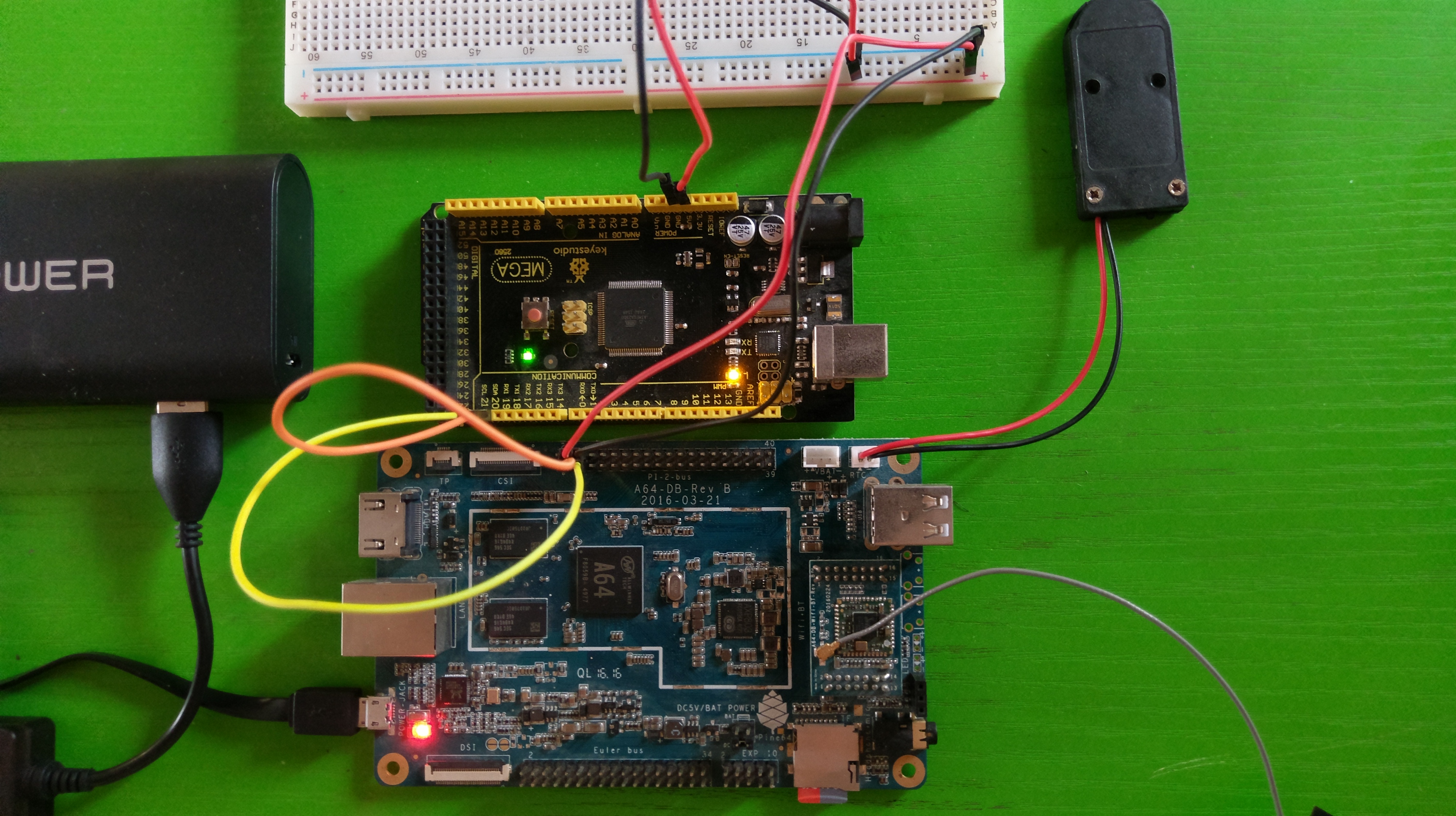
Although the PINE64 provides quite a decent number of GPIO pins, there are several reasons that you may want to have access to more pins. For example, the Arduino can provide an extra number of native PWM pins, or you may want to implement low-level control of a robot using the Arduino, with high-level operations being handled by the PINE. This post will cover how this can be achieved with the PINE64 and an Arduino Mega. We’ll also create a sketch for the Mega which for handling I2C communication. In the next post, we will write some C and C# code which will show how to send and receive data between the PINE and the Mega. Note that this can be done with any single board computer that supports I2C including any of the Raspberry Pis, the Beagleboard and others.
PINE64 connected to Arduino Mega over I2C
I2C stands for Inter-Integrated Circuit and it is a serial computer bus that enables communication between multiple devices that support the protocol. Every board that supports I2C will have 2 pins called SDA (serial data line) and SCL (serial clock line).
Pins 3 and 5 of the Pi 2 pinout on the PINE64 are the SDA and SCL pins respectively. On the Mega, they are pins 20 and 21. Connect the SDA and SCL pins from the PINE64 to the SDA and SCL pins respectively on the Arduino. I have also connected the 5V from the PINE to the Mega in order for the Mega to be powered by the PINE. If you decide to take this approach, one of the ground pins also has to be connected between both boards.
A closer look at the I2C connection between the PINE64 and the Arduino Mega
Before connecting the Mega, we’ll need to create and upload a sketch that will assign an I2C address which will be used to access the device. The sketch will make use of the Wire library which will be used for I2C communication. We will be making use of byte arrays to send and receive data over the I2C bus. You can come up with a fancy protocol for this, but I came up with the following simple rules.
Maximum length of 16 bytes.
First byte will always be the length (inclusive of the first byte) of the data sent or received.
Second byte is the command. We’ll support 3 simple commands, digital write (0x01 or 1), digital read (0x02 or 2) and analog write (0x03 or 3).
Third byte is the pin number.
For digital write only, fourth byte be a value of either 1 (for high) or 0 (for low).
For analog write only, the next four bytes after the third byte will store an integer value between 0 and 255 inclusive.
With that out of the way, let’s take a look at the sketch. First things first, define our constants and variables.
1
2
3
4
5
6
7
8
9
10
11
12
13
14
15
16
17
18
19
20
21
22
23
24
25
26
27
28
#include <Wire.h>
// I2C slave address
#define I2C_ADDRESS 0x08
// Custom I2C data commands
#define CMD_DIGITAL_WRITE 0x01
#define CMD_DIGITAL_READ 0x02
#define CMD_ANALOG_WRITE 0x03
// Pin states
#define IO_PIN_STATE_INPUT 0x01
#define IO_PIN_STATE_OUTPUT 0x02
// Buffer for reading and writing data from/to I2C
The code is straightforward. We define 0x08 as the I2C address that we want the Mega to use. We also define our commands, pin states (for digital read / write), buffers for storing data to be sent and received and other variables that will be used. The ioPins array is a list of all the pins available on the Mega. This will need to be changed to match the board that the sketch will be uploaded to. The ioPinStates is a pseudo hashmap which will map the pin number (used as the array index) to one of the defined pin states (IO_PIN_STATE_INPUT or IO_PIN_STATE_OUTPUT). We’re keeping track of the pin states so that we can activate the pins on demand, instead of activating them all at once in the setup() function.
1
2
3
4
5
6
7
8
9
10
11
12
13
14
15
16
17
18
19
20
21
22
voidsetup(){
// put your setup code here, to run once:
Wire.begin(I2C_ADDRESS);
Serial.begin(9600);
Wire.onReceive(onDataReceived);
Wire.onRequest(onDataRequested);
}
voidloop(){
}
boolisPinValid(intpin){
for(inti=0;i<ioPinCount;i++){
if(ioPins[i]==pin){
returntrue;
}
}
returnfalse;
}
The setup function simply initialises the Wire library using the specified I2C address, and enables Serial output which will be used to output debug messages. Wire.onReceive registers the onDataReceived function which will be called when data is sent from the PINE64, while Wire.onRequest registers the onDataRequested function which will be called when the PINE64 requests data from the Mega. The isPinValid function is a helper method which checks if the pin specified as the parameter is valid for the board. It checks the pin against the ioPins array that we defined earlier.
Next is the onDataReceived function which handles most of the work. It accepts an argument which represents the number of bytes that were received.
1
2
3
4
5
6
7
8
9
10
11
12
13
voidonDataReceived(intbyteCount){
inti=0;
intidx=0;
while(Wire.available()){
bytes[idx]=Wire.read();
if((idx+1)==bytes[0]){// Length received
intlen=(int)bytes[0];
if(len<3){
Serial.print("Invalid data received.");
return;
}
The while loop checks if there is data available from the Wire library. If there is, the absolute minimum number of bytes received that can be considered valid based on the rules we defined earlier is 3 (length, command, pin). If the number of bytes received is less than 3, then the function ends at that point and output is written to the Serial console. The next step is to use a switch statement to check and handle the command that was received. The second byte (index 1) contains this data.
1
2
3
4
5
6
7
8
9
10
11
12
13
14
15
16
17
18
19
20
21
22
switch(bytes[1]){
caseCMD_DIGITAL_WRITE:
if(len<4){
Serial.println("Incomplete digital write data.");
return;
}
thisPin=(int)bytes[2];
if(!isPinValid(thisPin)){
Serial.println("Invalid pin specified for digital write.");
return;
}
// do digital write
if(ioPinStates[thisPin]!=IO_PIN_STATE_OUTPUT){
pinMode(thisPin,OUTPUT);
ioPinStates[thisPin]=IO_PIN_STATE_OUTPUT;
}
digitalWrite(thisPin,bytes[3]);
break;
For digital write, the minimum number of bytes to be considered valid is 4 (length, command, pin, value). The function is terminated if we received less than 4 bytes for the command. The isPinValid is called to check if the pin received is valid, and if it isn’t, the function ends at that point. Next thing to be done is to check if the pin has been activated. We make use of the ioPinStates array to do this making use of the pin number as the index. If the pin has not yet been activated (IO_PIN_STATE_OUTPUT), then we activate the pin using pinMode. Once this check is complete, we can call digitalWrite using the pin and the value specified.
1
2
3
4
5
6
7
8
9
10
11
12
13
14
15
16
17
18
19
20
21
caseCMD_DIGITAL_READ:
if(len<3){
Serial.println("Incomplete digital read data.");
return;
}
thisPin=(int)bytes[2];
if(!isPinValid(thisPin)){
Serial.println("Invalid pin specified for digital read.");
return;
}
if(ioPinStates[thisPin]!=IO_PIN_STATE_OUTPUT){
pinMode(thisPin,OUTPUT);
ioPinStates[thisPin]=IO_PIN_STATE_OUTPUT;
}
lastReadCommand=CMD_DIGITAL_READ;
lastReadPin=thisPin;
break;
Digital read also follows the same set of steps as digital write (validate date length, validate pin, check pin state) but we will call the actual digitalRead function in onDataRequested. What we do here is store the command and the pin in variables (lastReadCommand and lastReadPin respectively) which we can then make use of in onDataRequested.
1
2
3
4
5
6
7
8
9
10
11
12
13
14
15
16
17
18
19
20
21
22
23
24
25
26
27
caseCMD_ANALOG_WRITE:
if(len<7){
Serial.println("Incomplete analog write data.");
return;
}
thisPin=(int)bytes[2];
if(!isPinValid(thisPin)){
Serial.println("Invalid pin specified for analog write.");
return;
}
analogValue=0;
analogValue=(uint32_t)bytes[3]<<24;
analogValue|=(uint32_t)bytes[4]<<16;
analogValue|=(uint32_t)bytes[5]<<8;
analogValue|=(uint32_t)bytes[6];
if(analogValue<0||analogValue>255){
Serial.println("Invalid value specified for analog write.");
return;
}
analogWrite(thisPin,analogValue);
break;
Similar to digital write, analog write follows a couple of steps (validate data length and validate pin). We don’t need to check or set the pin state before calling the analogWrite function. We check that the value is between 0 and 255 inclusive before calling analogWrite with the pin and the value as the arguments.
1
2
3
4
5
6
7
8
9
10
11
default:
Serial.println("Unrecognised command.");
break;
}
idx=0;
}
idx++;
}
}
If the data sent did not match any of the defined commands, the code falls back to the default statement which outputs Unrecognised command. to the serial command, and then the onDataReceived function will be called again when new data is received.
Finally, we have the onDataRequested function which makes use of lastReadCommand and lastReadPin. The function is straightforward, as it uses the Wire library to send data back to the PINE following our simple rules.
1
2
3
4
5
6
7
8
9
10
11
12
voidonDataRequested(){
switch(lastReadCommand)
{
caseCMD_DIGITAL_READ:
// Send the value over I2C
sendBytes[0]=3;// length
sendBytes[1]=lastReadPin;// the pin that was read
sendBytes[2]=digitalRead(lastReadPin);// the pin value (0/1)
Wire.write(sendBytes,sendBytes[0]);
break;
}
}
And that’s it! Compile the sketch using the Arduino IDE and then upload it to your board. Connect your Arduino to the PINE after the sketch is successfully uploaded, and boot up the PINE. You can obtain the full code listing for the sketch at https://gitlab.com/akinwale/nanitei2c/blob/master/nanitei2c_mega.ino.
Install i2c-tools using sudo apt-get install i2c-tools. By default, only root can use the I2C commands, but you can add the user account with useradd -G i2c ubuntu (replace ubuntu with the username that you want to use to access I2C). Reboot the PINE and then scan the I2C bus with the command, i2cdetect -y 1. You should get output should be similar to the following:
1
2
3
4
5
6
7
8
9
0123456789abcdef
00:----------08--------------
10:--------------------------------
20:--------------------------------
30:--------------------------------
40:--------------------------------
50:--------------------------------
60:--------------------------------
70:----------------
Based on this output, we can see that the Mega was recognised over the I2C bus with the configured address in our sketch (0x08 or 8). With this, we have access to the extra pins which we will be able to control directly from the PINE. That’s pretty neat. In the next post, we will write the C and C# code for the PINE for handling I2C communication.
Similar to the Raspberry Pi, GPIO pins on the PINE64 can be controlled through sysfs. You can refer to my previous post which goes into the concept in detail, and the C# code remains the same for the PINE64. However, with the longsleep Ubuntu image, root access is required to control the GPIO pins. You will need to grant the necessary permissions in order to be able to control GPIO pins as a normal user.
Granting user permissions We’ll assume that we want to be able to control the pins as the default ubuntu user. Follow these steps to grant the necessary permissions.
Create a user group called gpio. groupadd gpio
Add the ubuntu user to the gpio group. useradd -G gpio ubuntu
Add a udev rule to run chown on the sysfs files. The chown command will set group ownership to the gpio group. Adding the udev rule will run the chown command automatically whenever you export a pin. Create a file called 99-com.rules in /etc/dev/rules.d and paste the following contents.
Physical pin to GPIO number mapping I took some time to test the physical pins on the PINE in order to determine the sysfs gpio numbers and came up with this table. As an example, physical pin 22 on the Pi 2 pinout corresponds to /sys/class/gpio/gpio79.
I worked on a project recently where I had to allow XMLHttpRequests from a different domain. I initially thought about adding the necessary Access-Control headers at the controller level, but after doing some reading, it turned out it was a better idea to make use of a dispatcher filter. However, dispatcher filters would only apply prior to CakePHP 3.3 since they are now deprecated.
Enter middleware, which I found to be quite familiar since I have made use of a similar concept in Express during my Node.js development. Think of middleware as reusable components which you can use to handle your web requests and modify responses.
The CakePHP middleware classes should be placed in the src/Middleware folder. You can create the folder if it doesn’t already exist in your project.
We’ll create a class in the Middleware folder called CorsMiddleware.php.
The code listing is pretty straightforward. The response is modified with the necessary headers to enable the cross origin requests to be successfully handled by the browser.
You can modify the header values as you see fit, like limiting the Access-Control-Allow-Origin header to specific domains – the wildcard (*) allows requests to be accepted from all domains – or the the request methods to just GET and POST, or the allowed request headers.
To make use of the cors middleware, modify src\Application.php and add the middleware using: $middleware->add(new CorsMiddleware())
And that’s all there is to it. There are more details about what you can do with middleware in the CakePHP documentation, so be sure to check it out.
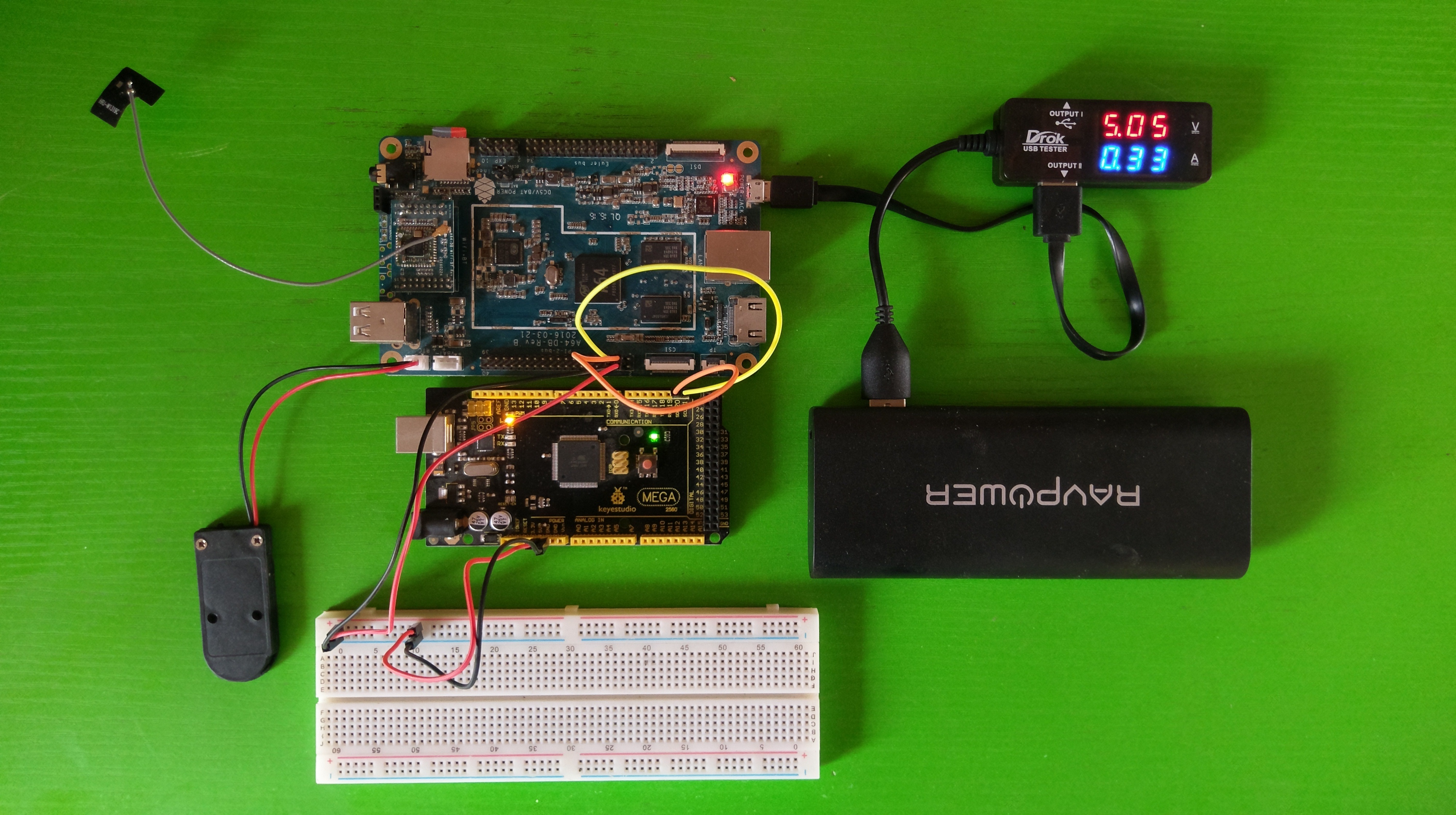
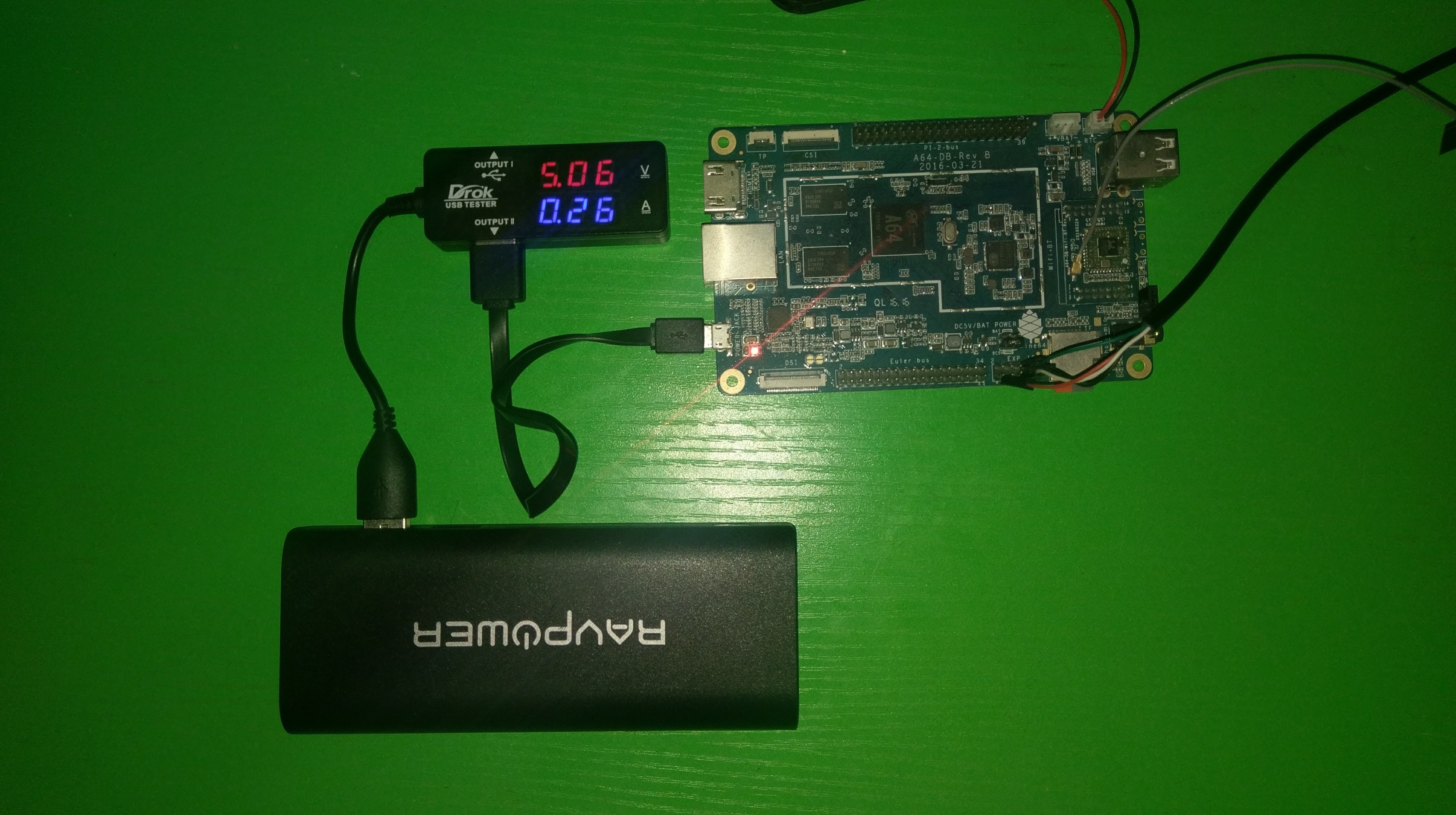
I got a DROK digital multimeter and I decided to find out just how much power the PINE64 consumes running headless.
PINE64 connected to RAVPOWER powerbank through DROK multimeter
The measurements were taken on my 1GB PINE64 running longsleep’s Ubuntu image. The measured voltage from the powerbank is 5.06V.
CPU @ 1152MHz
CPU @ 480MHz
WiFi / BT module plugged in
260mA (1.32W)
200mA (1.01W)
WiFi / BT module removed
250mA (1.27W)
190mA (0.96W)
This is not by any means a proper scientific test, but it gives an idea of what to expect. Got any tips for reducing power consumption? Feel free to share them in the comments below.
Hello and welcome to Antinormal. I used to maintain this as a personal blog but I decided to start all over since I wanted to take things in a different direction. I hope to make useful posts going forward.
My name is Akinwale and my favourite things are computers, video games, good movies and books. As I’ve grown older, I find that I haven’t had much time to play games anymore, but I still play The Division fairly regularly. The only other games I have played this year are Deus Ex: Mankind Divided and X-COM 2.
I like science fiction, technology and programming.
Thank you for reading! Comments and feedback are welcome.